
Scaffold

Inactive Publication Date: 2009-03-19
TEIJIN LTD
View PDF4 Cites 18 Cited by
  • Summary
  • Abstract
  • Description
  • Claims
  • Application Information

AI Technical Summary

Benefits of technology

[0007]It is an object of the present invention to provide a scaffold which is a high-density assembly of fibers and suitable for cell growth. It is another object of the present invention to provide a scaffold for cell growth which has excellent mechanical strength. It is still another object of the present invention to provide a scaffold which can grow a cell well. It is a further object of the present invention to provide a process of manufacturing the scaffold. It is a still further object of the present invention to provide a method of growing a cell by using the scaffold. It is a still further object of the present invention to provide a method of regenerating a living tissue by using the scaffold.

Problems solved by technology

As for a structure obtained by the freeze-drying or phase separation technique, the shape of each pore is isolated and the intrusion of a cell is difficult.
Thus, the structure is unsatisfactory as a scaffold.
A structure obtained by the foaming technique also has a problem that the intrusion of a cell is difficult because pores are isolated independently.
However, pores formed by this method are not continuous and there is limitation to cell growth.
This method has a defect that, when the fibers are accumulated to a predetermined thickness or more, an electrode is covered with the accumulated product as the fibers are collected on a planar collection electrode, whereby it is difficult to maintain a certain potential difference and the density of the accumulated fibers changes in the accumulation direction.

Method used


Image

  • Scaffold
  • Scaffold
  • Scaffold

Examples


example 1

Preparation of Dope

[0087]A lactic acid-glycolic acid copolymer (molar ratio=50 / 50) was dissolved in a mixed solvent of methylene chloride and ethanol to prepare a 15 wt % dope.

(Spinning)

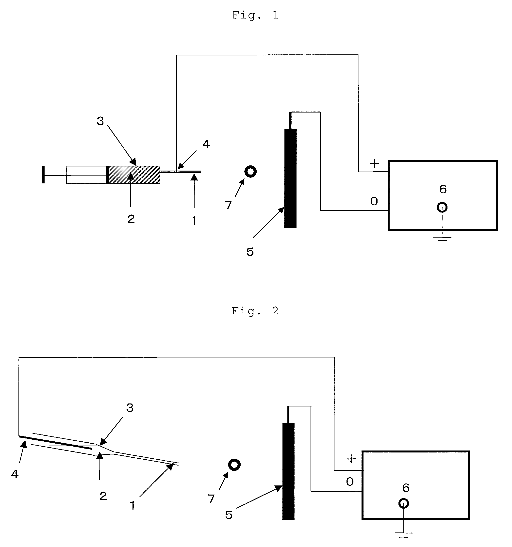
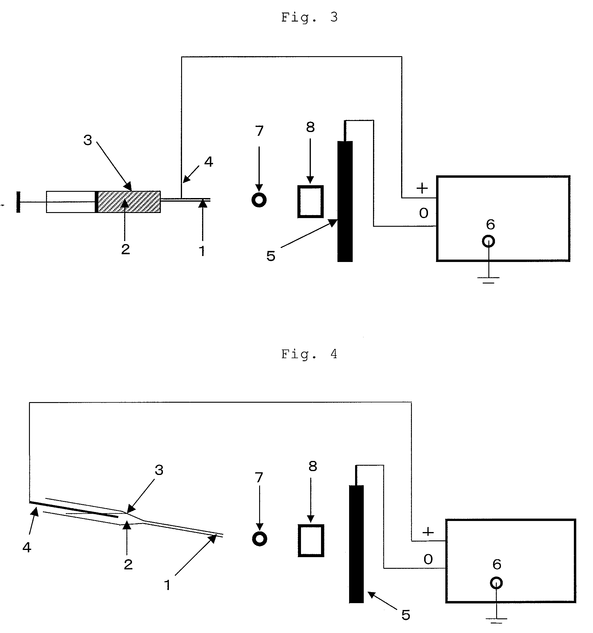
[0088]A cylindrical roll composed of an assembly of fibers was obtained by the electrospinning method using the apparatus shown in FIG. 4. The inner diameter of the nozzle (1) was 1.3 mm. The distance from the nozzle (1) to the winder (7) was 20 cm, and the distance from the nozzle (1) to the static electricity removing apparatus (8) was 35 cm. Applied voltage was 15 kV. The winder (7) and the static electricity removing apparatus (8) manufactured by Kasuga Denki Co., Ltd. were installed between the nozzle (1) and the negative electrode (5). The positive electrode (4) was inserted into the dope holding tank (3). The revolution of the winder (7) was set to 100 rpm.

[0089]The dope was fed to the dope holding tank (3), the distance between the nozzle (1) and the negative electrode (5) was adjusted, and f...

example 2

Preparation of Dope

[0096]The same lactic acid-glycolic acid copolymer as in Example 1 was used to prepare a 10 wt % dope.

(Spinning)

[0097]A cylindrical roll composed of an assembly of fibers was obtained in the same manner as in Example 1 except that the delivery time was set to 90 minutes and the heat treatment was carried out at 70° C. for 10 minutes.

(Cutting Out)

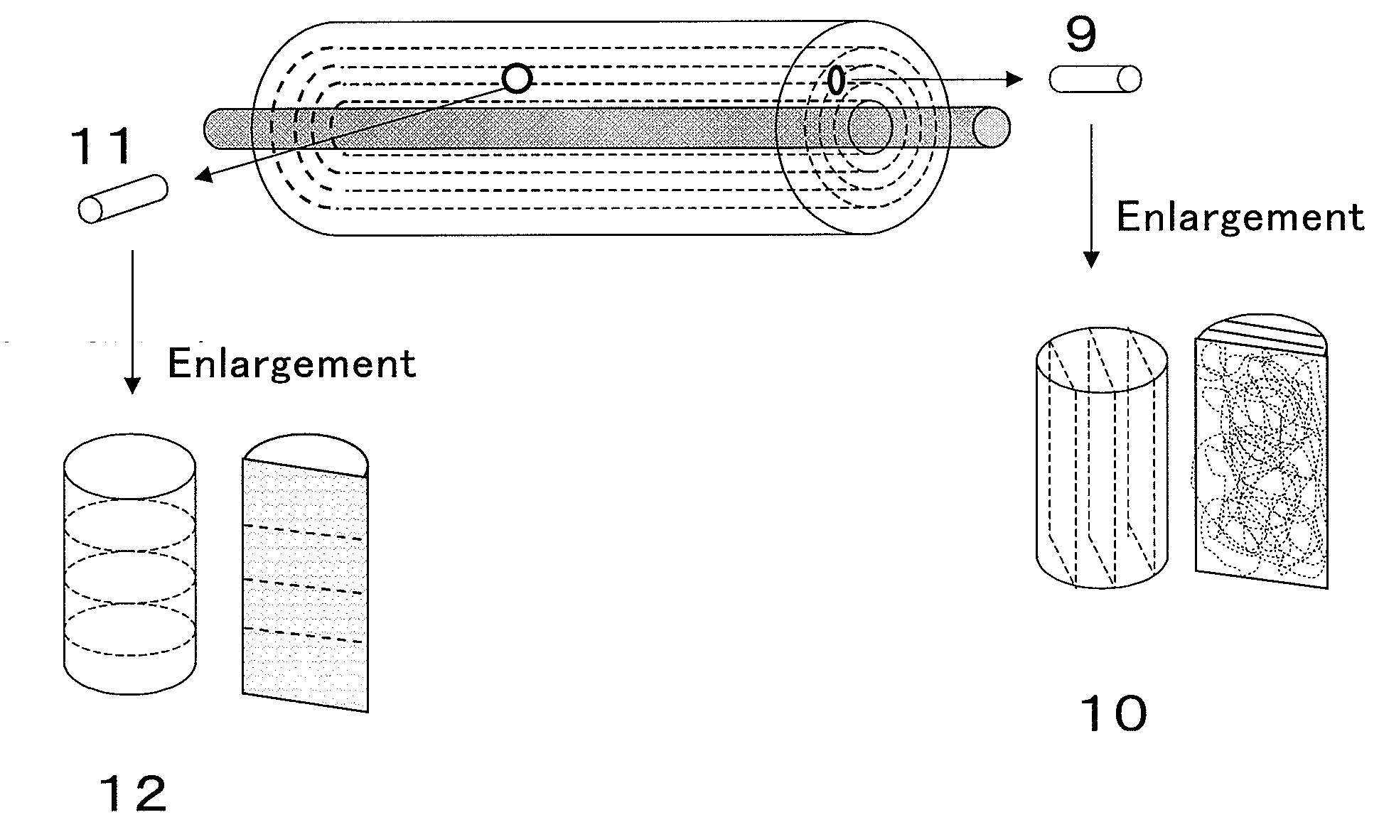
[0098]A cylindrical scaffold having a diameter of 5 mm and a height of 5 mm corresponding to 10 in FIG. 5 was cut out from the obtained roll in the same manner as in Example 1. FIG. 6 (top end face) and FIG. 7 (bottom end face) show microphotographs (15 magnifications) of a section parallel to the end faces of the scaffold corresponding to 10 in FIG. 5. It is seen that the fibers were accumulated in layers.

(Evaluation of Characteristic Properties)

[0099]The characteristics properties of the scaffold were evaluated in the same manner as in Example 1. The results are shown in Table 1.

(Biological Evaluation of Scaffold)

(Prepar...

example 3

Manufacture of Scaffold

[0106]The operation of Example 2 was repeated to obtain a cylindrical scaffold having a diameter of 5 mm and a height of 5 mm corresponding to 12 in FIG. 5. The measurement results of the characteristic properties of the scaffold are shown in Table 1.

[0107]FIG. 10 shows a photomicrograph (200 magnifications) of a section perpendicular to the end surface of the scaffold corresponding to 12 in FIG. 5. It is seen that the fibers are aligned in a plane direction. FIG. 11 (top end surface) and FIG. 12 (bottom end surface) show photomicrographs (15 magnifications) of a section parallel to the end faces of the scaffold corresponding to (12) in FIG. 5. It is seen that the fibers are accumulated densely like the mesh of a net.

(Biological Evaluation)

[0108]A cell was cultured in the same manner as in Example 2 except that the obtained scaffold was used to measure the amount of DNA. The result is shown in Table 2. FIG. 13 and FIG. 14 show photomicrographs of the stained s...


PUM

PropertyMeasurementUnit
Diameteraaaaaaaaaa
Densityaaaaaaaaaa
Areaaaaaaaaaaa

Abstract

To provide a scaffold having excellent mechanical strength and cell growth capability and is suitable for use as a cell culture medium or a prosthetic material.The present invention relates to a scaffold composed of an assembly of fibers and having a 3-D structure consisting of two end faces and a side face, wherein(1) the fibers are aligned in a plane direction;(2) the fibers have a diameter of 0.05 to 50 μm;(3) the fibers are essentially composed of a biocompatible polymer; and(4) the scaffold has an apparent density of 95 to 350 kg / m3.

Description

TECHNICAL FIELD[0001]The present invention relates to a scaffold used for cell growth. The present invention relates to a scaffold which is composed of an assembly of fibers and suitable for use as a prosthetic material or a cell culture medium.BACKGROUND OF THE ART[0002]As an approach to the treatment of a greatly damaged living tissue, active researches into regenerative medicine for the reconstruction of an original living tissue by making use of the differentiation and proliferation of a cell are now under way. When a cell differentiates or grows in vivo, an extracellular matrix serves as a scaffold to construct a tissue. However, when a tissue is greatly damaged, it must be compensated for by an artificial or natural material until the cell itself produces a matrix. That is, a scaffold (prosthetic material) is an important factor for providing the optimum environment for the construction of a tissue. The requirements for this scaffold include 1) bioabsorption, 2) cell adhesion,...

Claims


Application Information

Patent Timeline
IPC IPC(8): A61B17/08A61B19/00D04H3/07
CPCA61L27/14C12M25/14A61L27/50A61L27/56A61L27/58C12N5/0068C12N2533/30C12N2533/40D01F6/04D01F6/22D01F6/66D04H3/07A61L27/18D01D5/0007C08L67/04C12N11/04C12N5/06
Inventor FUKUTOMI, CHIAKIKANEKO, HIROAKIKITAZONO, EIICHIKAYASHIMA, MIKANAKAYAMA, MIYUKI
Owner TEIJIN LTD
Learn More