Optical coupler devices, methods of their production and use

Inactive Publication Date: 2009-03-26
NKT PHOTONICS
View PDF12 Cites 49 Cited by
  • Summary
  • Abstract
  • Description
  • Claims
  • Application Information

AI Technical Summary

Benefits of technology

[0021]A further problem of fused, tapered fibre bundles is that it is difficult to package these, since the tapered region comprises an uncoated waveguide region. This region typically being solid glass surrounded by air (the wa

Problems solved by technology

A common problem in fibre optics is to launch light into a fibre efficiently.
A specific problem is to launch light from a pump-diode-laser with a large spot size and relatively low numerical aperture into a double clad fibre laser with a small area and large numerical aperture.
This approach has the disadvantage that only one pump fibre can be used.
Also, such a solution typically has only a coupling efficiency of 80-90%, has high reflections, is sensitive to mechanical drift and instability and sensitive to contamination.
Finally, such solution makes packaging design for a commercial device complicated and expensive.
The solution of bulk optics has a number of problems.
One problem is related to difficulties in achieving coupling with low loss.
Another problem is to achieve good coupling for a wide range of wavelengths.
A third problem is mechanical stability.
Fabrication of devices using bulk optics is also relatively complicated.
Furthermore, reflection from the multiple glass surfaces may deg

Method used


Image

  • Optical coupler devices, methods of their production and use
  • Optical coupler devices, methods of their production and use
  • Optical coupler devices, methods of their production and use

Examples


example 1

Optical Component

[0170]FIG. 3 schematically shows an embodiment 30 of the present invention; FIG. 3a being a longitudinal view showing how pump light 35 is coupled to a high NA, double clad fibre (first fibre) 31 from an off axis co-directional pump fibre (second fibre) 32 via a reflective element (reflector element) 33 and signal light 36 is coupled out from the high NA, double clad fibre (first fibre) through the reflective element (the reflector element has a coating that provides high reflection of the pump light, but not of the signal light). The first and second fibre(s) are hold together in a mounting tube 34. The number of second fibres is typically 3, 6, 12, 18, but it can be any number, such as 3 or larger, such as 6 or larger. FIG. 3b shows a cross section of the optical component including the ends of the first and second optical fibres 31, 32 (here 7 pump fibres) and the mounting tube 34 (along plane AA′ in FIG. 3a) to which the reflector element 33 is optically coupled...

example 2

Optical Component

[0172]The following is a description of preferred realizations of a unit which acts as a combined pump combiner and coupler. Furthermore it is described how such a combiner can be used in the realization of a fibre laser where the unit acts as a combined pump combiner / coupler, high reflector and output coupler.

[0173]The example consists of a description of the following elements of an optical component: Reflective element, first (passive pump) and second (active) optical fibres and a fibre holding element for positioning the first and second optical fibres relative to each other as well as a description of the coupler assembly and applications.

Reflector Element: Bulk Optical Mirror

[0174]In this realization the reflective element consists of a plano-convex element 120 with a plane 122 and a spherical surface 121, cf. FIG. 12. The spherical surface 121 is coated with a reflective coating. Such a coating could be either a dielectric coating consisting of a stack of thi...

example 3

Optimization of a Non Rotational Symmetric Aspheric Reflector Element

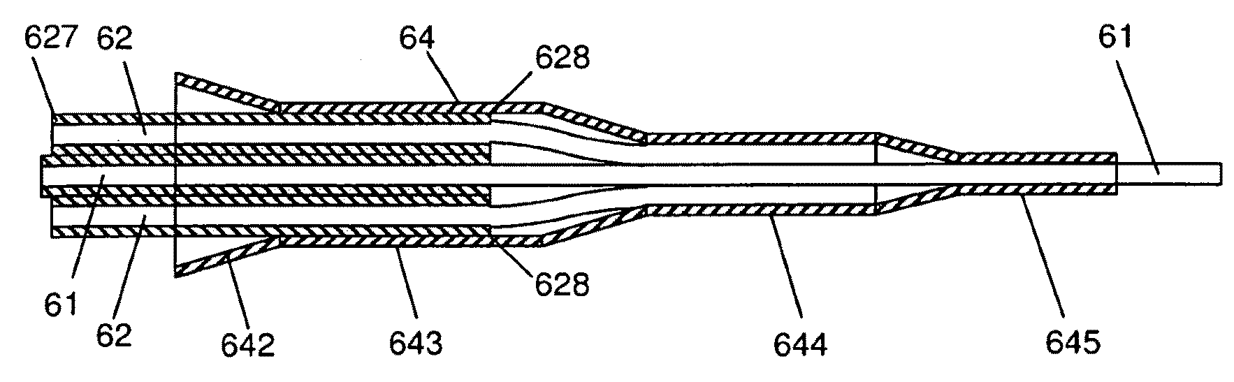
[0213]This following describes a procedure for designing a reflective end-cap coupler (reflector element) with a given shape or profile of the reflecting end-facet to couple light from a pump delivery fibre (second fibre) into a double-clad fibre (first fibre).

[0214]In order to design a suitable reflector we consider a ray 443 leaving an end 422 of the pump fibre 42 (second end) and consider the criteria which has to be fulfilled for the ray 444 to hit the end 413 of the first fibre 41 (first end) at an angle β within the acceptance cone of the first fibre, cf. FIG. 4.

[0215]Consider a ray 443 leaving the center of the pump core 421 of the pump fibre 42 at the second end 422 with an angle (90-α) to the y axis determined by the NA of the fibre, (referred to as NApump or as NA2). The line can be described by

y=tan(sin−1NApump)x+d=m1x+d.

[0216]This ray has to be reflected by the surface 441 (an end-facet of the reflecto...


PUM


Abstract

The present invention relates to an optical component comprising an acceptance fibre, e.g. a photonic crystal fibre, for propagation of pump and signal light, a number of pump delivery fibres and a reflector element that reflects pump light from the pump delivery fibres into the acceptance fibre. It is an object of the invention to provide a fibre coupler for coupling two or more light sources into a multi-clad (e.g. double clad) optical fibre, which has practical advantages with respect to handling, loss and back reflection. An object of the invention is achieved by an optical component comprising a) a first fibre having a pump core with an NA1, and a first fibre end; b) a number of second fibres surrounding said pump core of said first fibre, at least one of said second fibres has a pump core with an NA2 that is smaller than NA1, said number of second fibres each having a second fibre end; and c) a reflector element comprising an end-facet with a predetermined profile for reflecting light from at least one of said second fibre ends into the pump core of said first fibre. The invention further relates to articles comprising the optical component (e.g. a laser or amplifier), to methods of its production and use. The invention further relates to a rod-type optical fibre with optimized stiffness to volume ratio. The invention may e.g. be useful in applications such as fibre lasers or amplifiers, where light can be coupled efficiently from pump sources to an acceptance fibre, e.g. a double clad fibre, using the optical component. The invention specifically addresses optical fibre amplifiers where pump light and signal light are propagating in different directions (counter-propagating pump) within a double-clad optical fibre.

Description

TECHNICAL FIELD[0001]The present invention relates in general to coupling of light from one or more input waveguides to an output waveguide or output section of a waveguide having other physical dimensions and / or optical properties than the input waveguide or waveguides.[0002]The present invention relates to an optical component comprising an acceptance fibre, e.g. a photonic crystal fibre, for propagation of pump and signal light, a number of pump delivery fibres and a reflector element that reflects pump light from the pump delivery fibres into the acceptance fibre. The invention further relates to methods of producing the optical component, and articles comprising the optical component, and to the use of the optical component. The invention further relates to a rod-type optical fibre. The present invention is based on properties of multi-clad, such as double clad, optical fibres with relatively high numerical aperture, such as e.g. photonic crystal fibres (PCF).[0003]The inventio...

Claims


Application Information

Patent Timeline
IPC IPC(8): G02B6/26H01S3/30H04B10/12G02B6/036
CPCG02B6/02366G02B6/2817H01S3/094003H01S3/06729H01S3/06783H01S3/06708
Inventor NIKOLAJSEN, THOMAS
Owner NKT PHOTONICS
Why Eureka
Try Eureka