
High power optical fiber laser array holographic coupler manufacturing method

a manufacturing method and high-power technology, applied in the field of optical couplers, can solve the problems of high cost, inability to robustly apply approaches, and complexity of these systems and devices, and achieve the effects of low cost, high angular and spectral filtering selectivity, and ease of light and mechanical coupling

Inactive Publication Date: 2009-04-02
THE AEROSPACE CORPORATION
View PDF3 Cites 14 Cited by
  • Summary
  • Abstract
  • Description
  • Claims
  • Application Information

AI Technical Summary

Benefits of technology

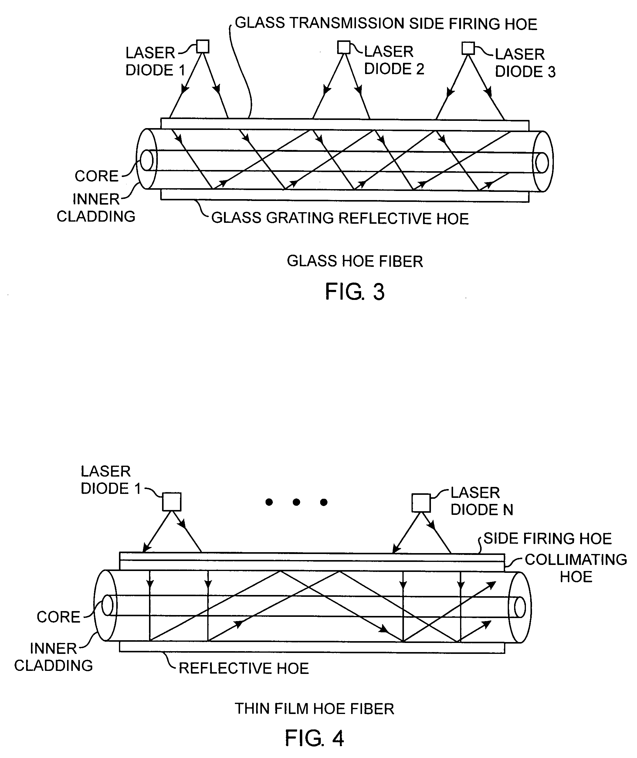
[0010]The invention is directed to a holographic optical element (HOE) coupler for coupling laser light into an optical fiber. The HOE coupler preferably couples laser light from an array of laser diodes into the optical fiber for higher levels of light amplification. The optical fiber can be, for example, a double-clad Yb and co-doped Er—Yb optical fiber. The HOE coupler is preferably a Bragg grating holographic optical coupler. Using the HOE coupler, the optical fiber is not required to have mechanical etching of coupling structures or embedded micro-mirrors within the fiber cladding. The holographic optical element (HOE) coupler is robust and can be designed for any wavelength in the preferred range of 300 nm to 2.7 μm, depending on the limitation of the holographic material used.
[0011]In a first aspect of the invention, the preferred HOE coupler includes a top laser light transmitting HOE and a bottom laser light reflective HOE. The top transmitting HOE is preferably a side firing HOE. The bottom HOE is preferably a reflective HOE. A top and bottom stripped double-clad optical fiber is sandwiched between transmitting and reflecting HOEs. The HOEs can be fabricated in commercially available high-efficiency photosensitive holographic recording materials. In a second aspect of the invention, the HOE coupler can be precisely manufactured using a HOE manufacturing method where interference fringes are created using an array of stepped micro lenses for generating an array of beams interfered with by a referenced beam using a beam splitter.
[0012]The HOE coupler advantages include ease of light and mechanical coupling, high angular and spectral filtering selectivity, optical power concentration, lightweight, thin in the 15 μm range, low cost, high coupling efficiency, insensitivity to misalignment, and simplicity of direct coupling into fibers with minimum perturbation of fiber structure. The HOE coupler has the advantage of being a universal coupler for all types of inner cladding shapes, sizes, and designs.
[0013]The HOE coupler serves to couple light from a laser diode or an array of laser diodes into a fiber through a thin film or glass of optical hologram indexed in the HOE coupler disposed on the sides of the optical fiber. The HOE can be sized to provide a universal coupling scheme for various inner-fiber cladding shapes, sizes, and designs, which can easily be integrated into existing fiber-laser systems. The HOE couplers provide a non-mechanical coupling scheme that avoids the embedding of special micro-mirrors or mechanical etching in the fiber cladding that degrades or weakens the physical structure of the fiber. The HOE coupler is a cost-effective holographic coupler that is insensitive to misalignment of the laser diodes. The use of a non-mechanical robust HOE coupler offers high coupling efficiency of greater than 80% with a minimum perturbation of fiber structure, for high-power laser array applications. These and other advantages will become more apparent from the following detailed description of the preferred embodiment.

Problems solved by technology

The complexities of these systems and devices required for laser pumping, geometrically grows with the pumping schemes employed and the amount of the required pumping power.
While some of these approaches are not robust, others suffer from excessive costs.
Still others suffer from alignment sensitivity, lack of compactness, scalability, and insufficient coupling efficiency, because of difficulty in coupling laser outputs into the fiber.
Some optical pumping approaches, such as the V-groove approach and the side-pumping approach, require the use of embedded micro-mirrors or mechanical etching in the inner fiber cladding that may weaken the fiber and pose a high risk to the mechanical integrity of the optical fiber.
In addition, as the demand for power increases, the use of these laser-pumping approaches disadvantageously requires redesigning the fiber coupling structure to accommodate the higher power.
Existing laser pumping coupling means are unsuitable for efficient pumping and coupling of laser light from an array of high power laser diodes into the optical fiber.

Method used


Image

  • High power optical fiber laser array holographic coupler manufacturing method
  • High power optical fiber laser array holographic coupler manufacturing method
  • High power optical fiber laser array holographic coupler manufacturing method

Examples


Embodiment Construction

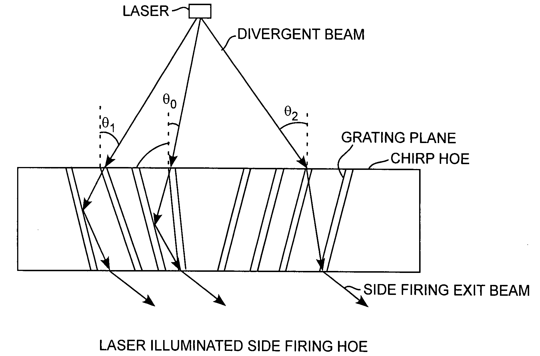
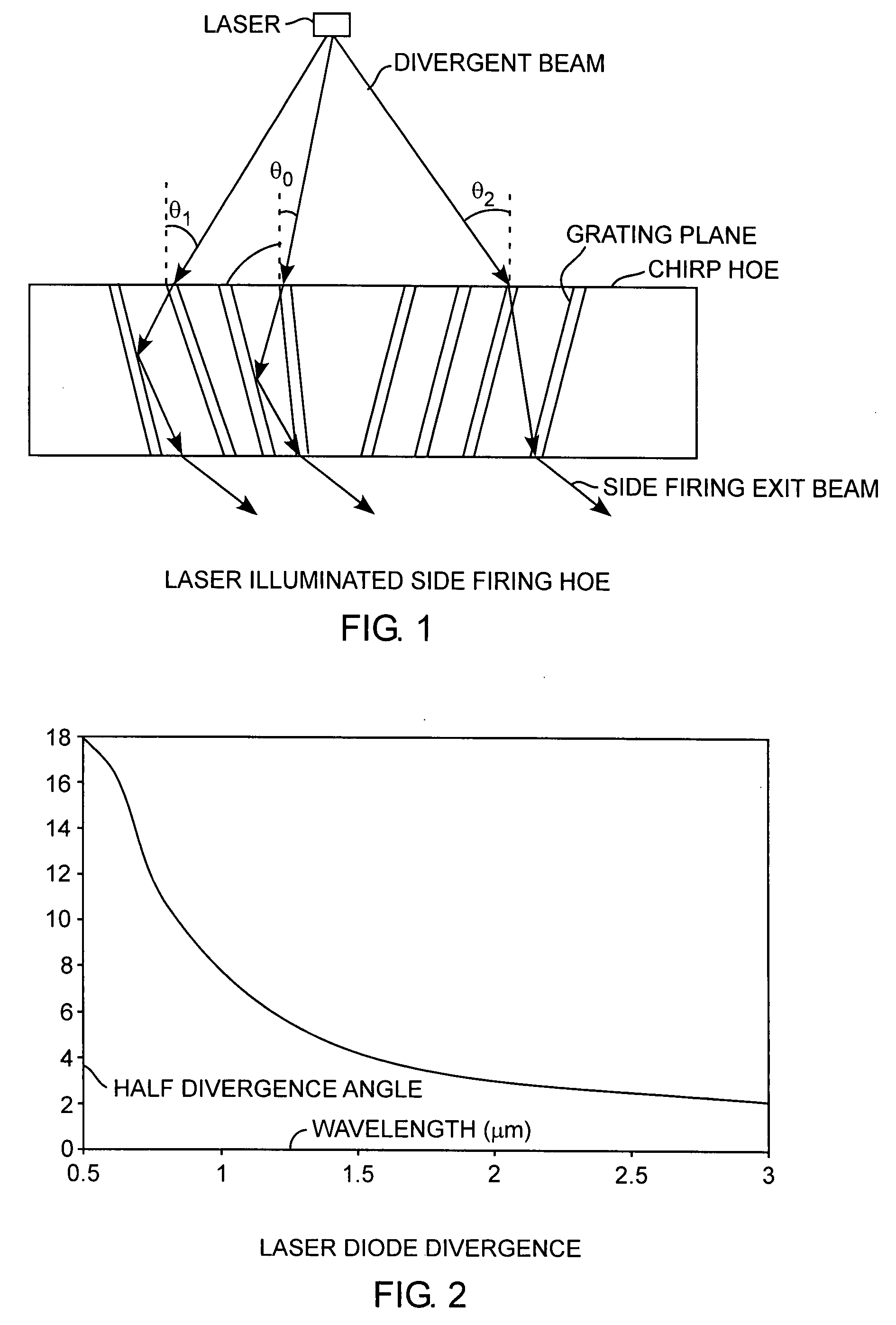
[0020]An embodiment of the invention is described with reference to the figures using reference designations as shown in the figures. Referring to FIGS. 1 and 2, a laser that may be a laser diode generates a divergent beam for illuminating a holographic optical element (HOE) that is preferably a chirped HOE having variable grating planes. The divergent beam is angularly spread for example through divergent beams having respective angles θ0, θ1, and θ2 for refracting and reflecting the divergent beam through the HOE so that the divergent beams exit the HOE as respective side firing exit beams. The side firing exit beams are preferably collimated side-firing exit beams. Depending on the preferred exit direction, a collimating HOE may be required to re-direct the side firing exit beams. The selectivity of the grating planes and the maximum acceptable laser diode divergence angles θ for various laser diode wavelengths determines the amount of light coupled into the double-clad fiber thr...


PUM


Abstract

A chirped grating is made in a thin film layer or a glass layer for producing a holographic optical element within the layer well suited for use as an optical coupler for coupling side fired laser light into optical fibers for laser light pumping of optical fibers with the grating made in the layer by generating interference fringes burned into the layer with interference fringes created from interfering a reference laser beam with a plurality of convergent laser beams from respective lenses of an array of lenses.

Description

REFERENCE TO RELATED APPLICATION [0001]The present application is related to applicant's copending application entitled High Power Optical Fiber Laser Array Holographic Couplers Ser. No. ______, filed ______, by the same inventor.FIELD OF THE INVENTION [0002]The invention relates to the field of optical couplers for optical fibers. More particularly, the present invention relates to optical couplers for coupling laser light into optical fibers.BACKGROUND OF THE INVENTION [0003]An array of high power laser light has been pumped into optical fibers for amplification along the optical fibers. Current approaches of injecting high power pump light into optical fibers include end-pumping, tapered fiber bundles, V-groove side pumping, embedded-mirror side pumping, geometrically multiplexed end-pumping, and a host of other systems. The complexities of these systems and devices required for laser pumping, geometrically grows with the pumping schemes employed and the amount of the required pu...

Claims


Application Information

Patent Timeline
Patent Type & Authority Applications(United States)
IPC IPC(8): G02B5/32
CPCG02B5/1876G02B5/32G03H2270/21G03H2001/0439G02B6/34
Inventor OKOROGU, ALBERT O.
Owner THE AEROSPACE CORPORATION
Learn More