Protective Film for Polarizing Plate

a technology of protective film and polarizing plate, which is applied in the direction of polarizing elements, instruments, transportation and packaging, etc., can solve the problems of poor moisture resistance and gas barrier performance of triacetylcellulose film, insufficient durability, heat resistance, mechanical strength of polarizing plate, etc., and achieves good visibility, fewer scratches, and excellent color reproduction

Active Publication Date: 2009-04-02
ZEON CORP
View PDF6 Cites 17 Cited by
  • Summary
  • Abstract
  • Description
  • Claims
  • Application Information

AI Technical Summary

Benefits of technology

[0018]The protective film for polarizing plate of the present invention has interference fringes hard to occur, excellent color reproduction, and fewer occurrences of scratches by friction, so laminating of the protective film on a polarizer can give a polarizing plate which will not cause defective visibility. Moreover, in using of the protective film for polarizing plate of the present invention, a phase difference of the polarizing plate is hardly changed by deformation due to a heat or stress, and obtained can be the polarizing plate which does not have light leakage, uneven color, coloring or the like in the vicinity of an edge of a display screen even if an undesirable and unexpected stress is applied.
[0019]Since the polarizing plate of the present invention in which deformation is hard to occur and a fewer scratches occur by friction, visibility is favorable. Also, the polarizer and the protective film are hard to be exfoliated from each other even in a severe environment. Moreover, the polarizing plate of the present invention gives hardly rise to light interference such as rainbow unevenness and coloring, and has fewer occurrences of scratches by friction, so visibility is favorable.
[0020]The polarizing plate of the present invention is suitable particularly for a large-area liquid crystal display or the like.

Problems solved by technology

However, the triacetyl cellulose film is poor in moisture proof and gas barrier performance, which does not allow the polarizing plate to be sufficient in durability, heat resistance, mechanical strength and the like.

Method used


Image

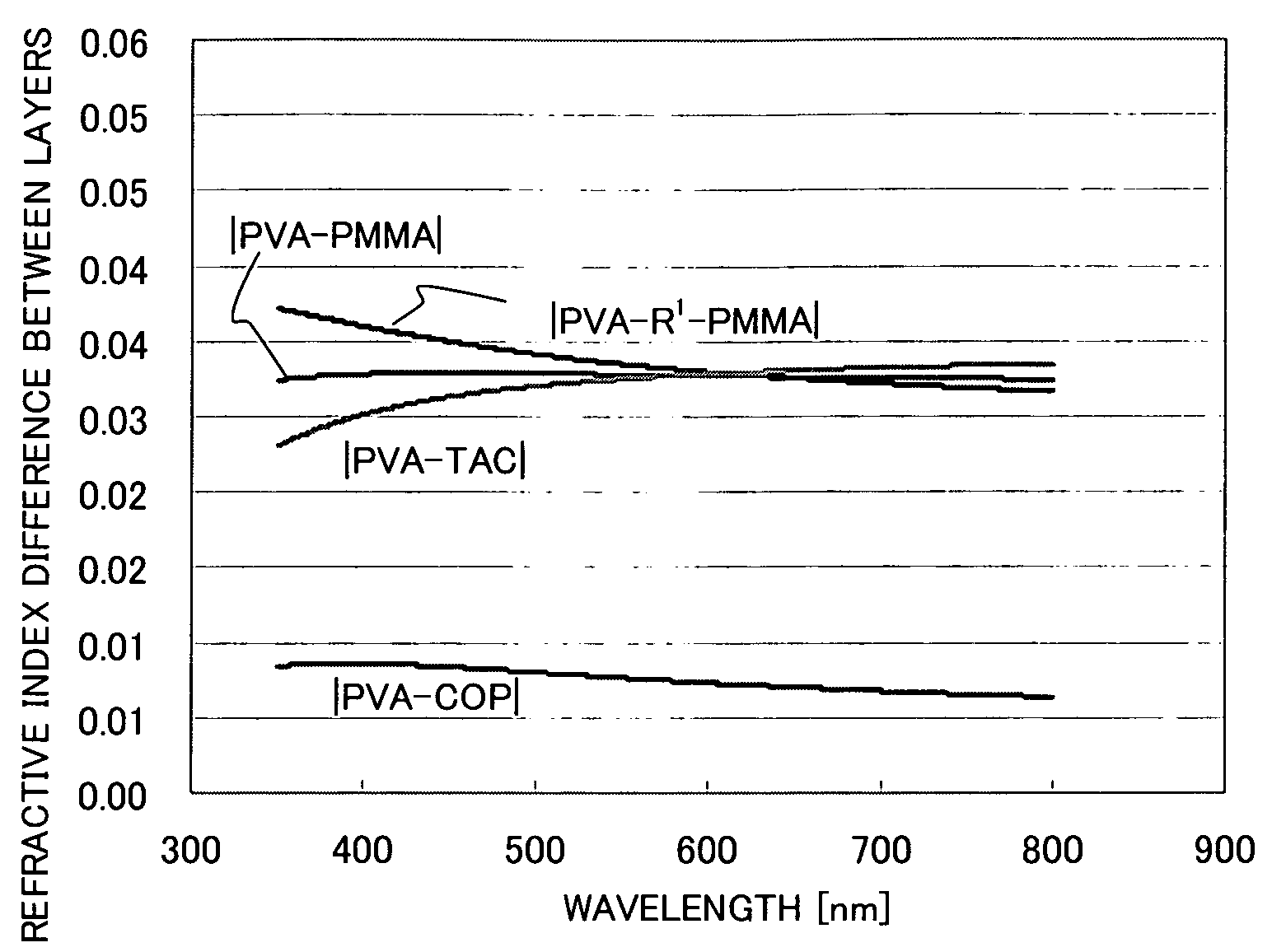
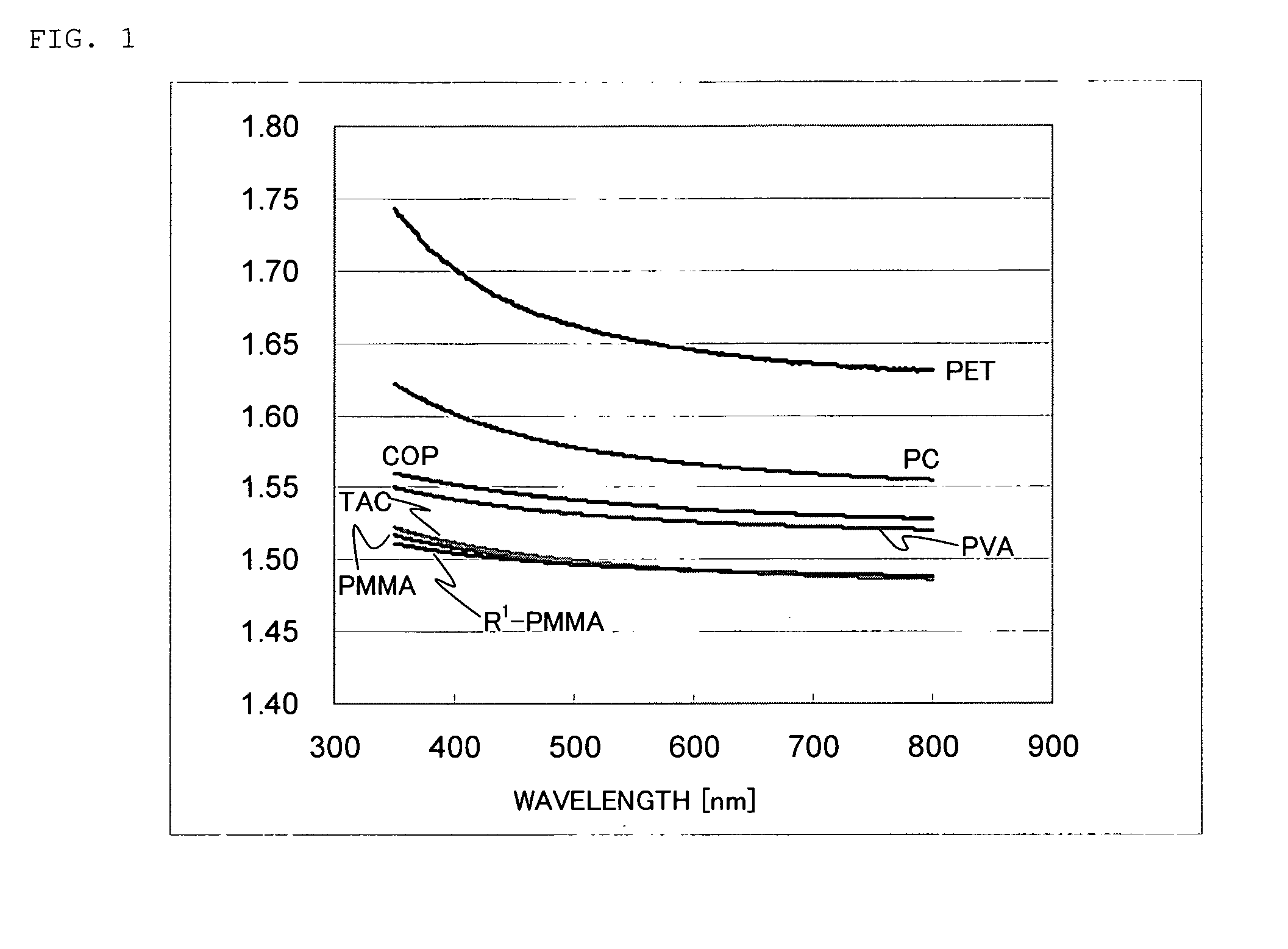
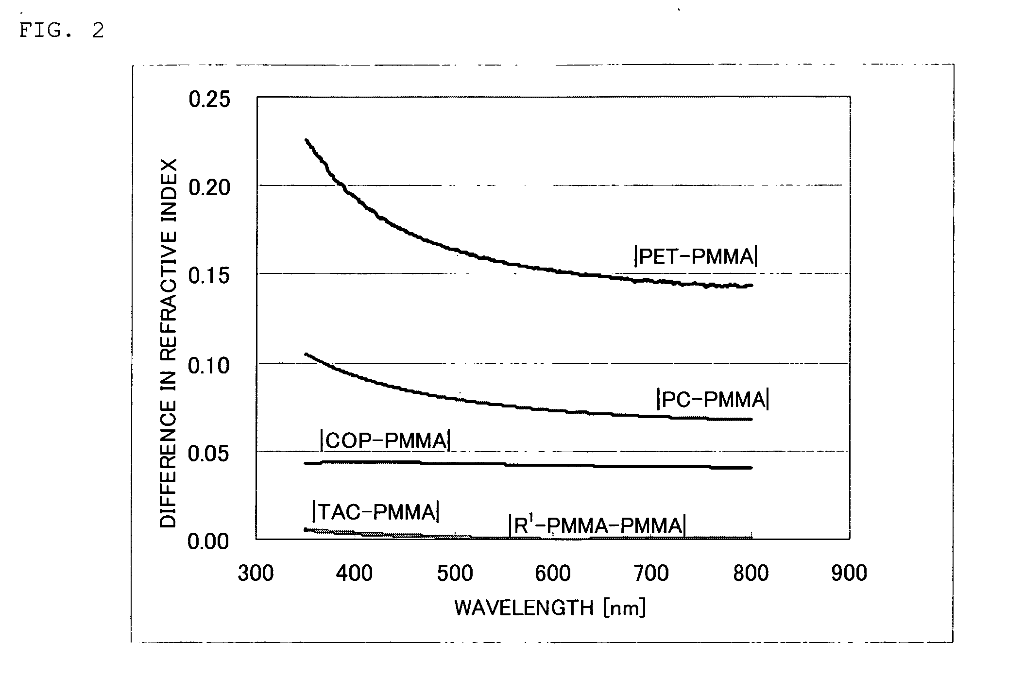
  • Protective Film for Polarizing Plate
  • Protective Film for Polarizing Plate
  • Protective Film for Polarizing Plate

Examples


examples

[0117]Examples and Comparative examples will be shown below in order to describe the present invention more specifically, but the present invention is not limited to the following embodiments but includes a case of four or more thermoplastic resin layers or a case of two layers, for example. Also, part and % are weight standard unless specifically noted.

(Preparation of Composition for Forming High Refractive-Index Layer (Hard-Coat Layer))

[0118]By a homogenizer, 30 parts of 6 functional urethane acrylate oligomer, 40 parts of butyl acrylate, 30 parts of isoboronyl methacrylate, and 10 parts of 2,2-diphenylethane-1-one were mixed, and 40%-methyl isobutyl ketone dispersion of antimony pentoxide particulate (average particle size of 20 nm, one hydroxyl group was bound to an antimony atom appearing on the surface of the pyrochlore structure) was mixed in a proportion that the weight of the antimony pentoxide particulate occupies 50 weight % of the whole solid content in the composition f...

example 1

Fabrication of Protective Film for Polarizing Plate

[0121]Polymethylmethacrylate resin (water absorption coefficient of 0.3%, photoelastic coefficient of −6.0×10⁻¹² Pa−1, haze of 0.08%, humidity expansion coefficient of 28 ppm / % RH, tensile elastic modulus of 3.3 GPa. Abbreviated as “PMMA”) was inputted to a double-flight type uniaxial extruder with a leaf-disk shaped polymer filter with an opening of 10 μm installed, and a molten resin was supplied to one of multi-manifold die with a die lip having surface roughness Ra of 0.1 μm at an extruder outlet temperature of 260° C.

[0122]On the other hand, an alicyclic olefin polymer (hydrogenated product of ring-opening polymer of a norbornene monomer, water absorption coefficient of less than 0.01%, photoelastic coefficient of 6.3×10⁻¹² Pa−1, haze of 0.02%, humidity expansion coefficient of less than 1 ppm / % RH, tensile elastic modulus of 2.4 GPa. Abbreviated as “COP”) was inputted to a double-flight type uniaxial extruder with a leaf-disk ...

example 2

[0127]On one face of a cellulose triacetate film with the thickness of 80 μm, 25 mL / m2 of 1.5 mol / L isopropylalcohol solution of potassium hydroxide was applied and dried at 25° C. for 5 seconds. Then, it was washed by running water for 10 seconds and the surface of the film was dried by blowing air of 25° C. at the end to obtain a film 2B in which only one face of the triacetyl cellulose film was saponified.

[0128]An acrylic adhesive was applied on one face of the protective film 1A for polarizing plate, while a polyvinyl alcohol adhesive was applied on the saponified face of the film 2B, and the protective film 1A for polarizing plate, the polarizer P and the film 2B were stacked in this order and bonded with the adhesive by the roll-to-roll method so as to obtain a polarizing plate 2. Evaluation results are shown in Table 1 and Table 2. The obtained polarizer was attached to a liquid crystal display so that the film 1A was on the side far from the liquid crystal panel.


PUM

PropertyMeasurementUnit
hazeaaaaaaaaaa
water absorption coefficientaaaaaaaaaa
widthaaaaaaaaaa

Abstract

A protective film for polarizing plate comprising k layers (k is an integer of 2 or more) of thermoplastic resin layer laminated, wherein
    • a refractive index ni(380) at a wavelength of 380 nm and a refractive index ni(780) at a wavelength of 780 nm in the i th thermoplastic resin layer as well as a refractive index ni+1(380) at a wavelength of 380 nm and a refractive index ni+1(780) at a wavelength of 780 nm in the i+1 th thermoplastic resin layer have a relationship in
ni(380)−ni+1(380)|−|ni(780)−ni+1(780)∥≦0.02
(where, i is an integer of 1 to k−1). A polarizing plate is obtained by bonding the protective film for the polarizing plate and a polarizer. And a liquid crystal display comprising the polarizing plate and a liquid crystal panel.

Description

TECHNICAL FIELD[0001]The present invention relates to a protective film for polarizing plate, a polarizing plate and a liquid crystal display, and particularly to a protective film for polarizing plate, a polarizing plate, and a liquid crystal display in which there is no deformation by separation or the like even under an environment of high temperature and high humidity; no defective visibility due to light leakage, uneven color, coloration or the like in the vicinity of an edge of a display screen but which is excellent in scratch resistance and suitable for a liquid crystal display and the like.BACKGROUND ART[0002]A polarizing plate used in the liquid crystal display or the like is a laminated body comprising a polarizer and a protective film.[0003]As the polarizer constituting the polarizing plate, used is usually a film obtained by having iodine or diachronic dye adsorbed to polyvinyl alcohol film made by a casting method and drawing the adsorbed film in a boric-acid solution....

Claims


Application Information

Patent Timeline
Patent Type & Authority Applications(United States)
IPC IPC(8): G02B1/08G02B5/00G02B5/30G02F1/1335
CPCG02B1/105G02F1/133528G02F2201/50Y10T428/1086Y10T428/24479Y10T428/24942Y10T428/1036Y10T428/105Y10T428/31928Y10T428/31855Y10T428/31913Y10T428/31935Y10T428/31938Y10T428/31909Y10T428/31786Y10T428/31721Y10T428/3192Y10T428/31507G02B1/14C09K2323/03C09K2323/035C09K2323/06G02B5/30G02F1/1335G02B1/11
Inventor YOSHIHARA, MASANORITOYOSHIMA, TETSUYAARAKAWA, KOHEI
Owner ZEON CORP
Why Eureka
Try Eureka