
Method of Producing High-Purity Hydrogen

a high-purity hydrogen and purification technology, applied in the direction of hydrogen separation using solid contact, dispersed particle separation, separation process, etc., can solve the problem of energy dependency, difficult to use this technique as a purification technique to yield such a high-purity hydrogen, and the known hydrogen psa process requires very large-scale facilities (very large-scale adsorption towers). the effect of low cost and small production system

Inactive Publication Date: 2009-05-07
KOBE STEEL LTD
View PDF4 Cites 2 Cited by
  • Summary
  • Abstract
  • Description
  • Claims
  • Application Information

AI Technical Summary

Benefits of technology

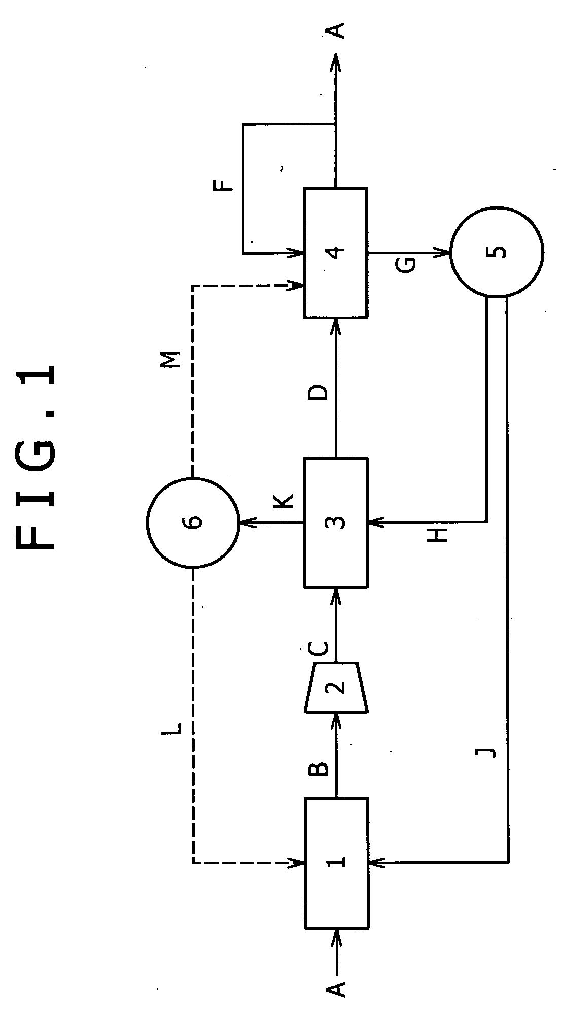
[0105][PSA Adsorbent Regenerating Step]: In the other PSA tower(s), the pressure in the PSA tower(s) is reduced from a high pressure to normal pressure, and a purge gas H is circulated so as to regenerate the adsorbent which has had a lowered adsorption ability due to the adsorption operation. The purge gas H can be, for example, a carbon monoxide adsorption tower offgas G which has been used for the regeneration of a carbon monoxide adsorbent packed in a carbon monoxide adsorption tower of the carbon monoxide remover 4. This will be illustrated in detail in the after-mentioned explanation of effective use of a carbon monoxide adsorption tower offgas. Thus, a carbon monoxide-containing hydrogen gas D can be continuously obtained while maintaining the adsorption ability of the adsorbent over long time by cyclically repeating a cycle including the unnecessary gas adsorbing step and the PSA adsorbent regenerating step in the two or more PSA towers of the PSA tower unit 3.
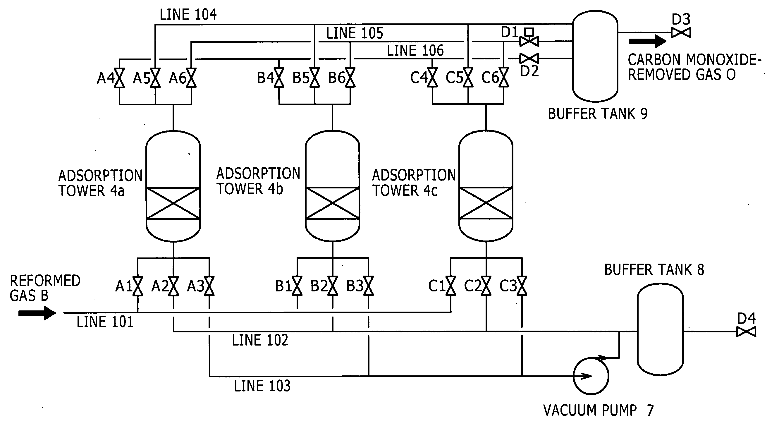
[0107]The carbon monoxide removing step according to the present invention uses a carbon monoxide remover 4 including two or more (three in the embodiment shown in FIG. 4) carbon monoxide adsorption towers each packed with a carbon monoxide adsorbent, as shown in FIG. 4. Hereinafter this step will be illustrated as dividing into a carbon monoxide adsorbing step and a carbon monoxide adsorbent regenerating step, and a switching operation of these steps will be explained.
[0108][Carbon Monoxide Adsorbing Step]: The carbon monoxide-containing hydrogen gas D is allowed to pass through the carbon monoxide remover 4 packed with a carbon monoxide adsorbent to remove carbon monoxide from the carbon monoxide-containing hydrogen gas D selectively by adsorption. The carbon monoxide adsorbent for use herein is preferably a material including a copper(I) halide and / or a copper(II) halide supported on at least one support selected from the group consisting of silica, alumina, activated carbon, graphite, and a styrenic resin, or a reduced product of this material, because this adsorbent chemically adsorbs carbon monoxide and has high selectivity to carbon monoxide. Among such materials, a material including copper(I) chloride supported on an alumina support is recommended, because this has high mechanical strength, a large carbon monoxide adsorptivity, and a high selectivity. Such a carbon monoxide adsorbent including a supported copper halide contributes to downsizing of the carbon monoxide remover 4, because the adsorbent has an adsorption capacity several times as much as those of known adsorbents such as zeolite molecular sieves, carbon molecular sieves, activated carbon, or active alumina.
[0109][Carbon Monoxide Adsorbent Regenerating Step]: To maintain the adsorption performance of the carbon monoxide adsorbent, the carbon monoxide adsorbent should be regenerated before a carbon monoxide concentration at an outlet of the carbon monoxide remover 4 increases up to a predetermined concentration (becomes breakthrough) in the carbon monoxide adsorbing step. The regeneration of the carbon monoxide adsorbent is carried out while circulating, as a purge gas, a gas substantially free from carbon monoxide, in order to desorb and remove carbon monoxide which has been adsorbed by an adsorption site. The regeneration (cleaning) is preferably carried out while heating the carbon monoxide adsorbent to temperatures of 40° C. to 150° C., because a desorption reaction of carbon monoxide is promoted with an elevating temperature. To satisfy these conditions, the gas substantially free from carbon monoxide for use as the purge gas may be a part F of a product hydrogen E. This may be heated before use by exchanging heat with the reformed gas B (namely, using the sensible heat of the reformed gas B) in the heat exchanger (not shown).
[0110][Switching Operation Between Carbon Monoxide Adsorbing Step and Carbon Monoxide Adsorbent Regenerating Step]: For each carbon monoxide adsorption tower, the carbon monoxide adsorbing step and the carbon monoxide adsorbent regenerating step must be alternately switched. However, the carbon monoxide adsorbing step should be carried out in at least one of the three towers at any time, in order to produce a high-purity hydrogen E continuously. It is recommended to carry out the carbon monoxide adsorbing step in two of the three towers and to carry out the carbon monoxide adsorbent regenerating step in the other one tower so that a carbon monoxide adsorption tower which has been in the carbon monoxide adsorbing step is switched to the carbon monoxide adsorbent regenerating step, and the regeneration is carried out sufficiently, because it takes much time to elevate the temperature of the carbon monoxide adsorbent to such a temperature that the carbon monoxide desorption reaction is activated. In addition, two towers (4a and 4b) in the carbon monoxide adsorbing step are connected in series, and the carbon monoxide-containing hydrogen gas D is allowed to pass through the two towers not in parallel but in series successively to remove carbon monoxide by adsorption (FIG. 4(a)). After elapse of a predetermined time and at the time when the upstream carbon monoxide adsorption tower 4a reaches complete breakthrough with carbon monoxide, the upstream carbon monoxide adsorption tower 4a is separated from the series connection, and a carbon monoxide adsorption tower 4c after the completion of regeneration of its adsorbent is connected downstream from the carbon monoxide adsorption tower 4b. Carbon monoxide is removed by adsorption using the series connection including the carbon monoxide adsorption towers 4b and 4c while carrying out regeneration of the adsorbent of the carbon monoxide adsorption tower 4a (FIG. 4(b)). Then, the operation proceeds to the state shown in FIG. 4(c) and returns to the state shown in FIG. 4(a), and the switching operation is repeated in this manner. Thus, a high-purity hydrogen E from which carbon monoxide has been sufficiently removed can be always obtained without occurrence of breakthrough (increase of the carbon monoxide concentration at the outlet), by connecting two towers in series and carrying out regeneration sequentially from the upstream one of the two. This is because the downstream carbon monoxide adsorption tower always has some residual carbon monoxide adsorption capacity. In addition, cost reduction in adsorbent and downsizing of facilities can be realized, because the upstream carbon monoxide adsorption tower can be used until its adsorption capacity is substantially completely finished up, and this eliminates the need of excessive packing of the adsorbent in each adsorption tower.
[0112][Effective Use of Carbon Monoxide Adsorption Tower Offgas]: The carbon monoxide adsorption tower offgas G as a gas after the regeneration of the carbon monoxide adsorbent in the carbon monoxide adsorbent regenerating step is preferably temporarily stored in a buffer tank 5 and is effectively used, for example, in the following manner.

Problems solved by technology

Combined with measures against global warming, a departure from dependency of energy on crude oil has become a world-wide important issue, and efforts to yield practically usable fuel cells using hydrogen gas as an energy source are stepping up not only in European industrialized countries, where efforts for environmental protection have preceded, but also in the United states of America, and Japan and other Asian countries.
However, it is difficult to use this technique as a purification technique to yield such a high-purity hydrogen as to be required in on-vehicle fuel cells, because the technique is not a technique of removing CO2, H2O, and CH4 as other impurities than carbon monoxide.
As problems in the hydrogen PSA process, the known hydrogen PSA process requires very large-sized facilities (very large-sized adsorption towers), because it is difficult to remove carbon monoxide which is contained in a crude hydrogen in a content of up to about 1%, and a large quantity of adsorbents is required.
In addition, cost for purifying hydrogen is increased, because the recovery of the product hydrogen is not sufficiently high.
According to these techniques, however, all impurity gases including carbon monoxide in hydrogen are removed by the hydrogen PSA process, and adsorbents have insufficient adsorption capacities of CO gas.
Thus, there is limitation in downsizing of facilities.
In addition, the hydrogen recovery is still insufficient, although improvements by the various techniques have been studied.
Although this technique is effective for downsizing the hydrogen PSA system, it causes a lowered hydrogen recovery when considered as a whole system, because excessive oxygen is introduced in selective oxidation of carbon monoxide, and oxygen which has not reacted with carbon monoxide reacts with hydrogen to thereby consume hydrogen.

Method used


Image

  • Method of Producing High-Purity Hydrogen
  • Method of Producing High-Purity Hydrogen
  • Method of Producing High-Purity Hydrogen

Examples


embodiment 1

[0097]One of embodiments is shown in the flow chart of FIG. 1 by way of example. In FIG. 1, the numeral 1 represents a reforming unit 1 that reforms a reformable raw material to yield a hydrogen-rich reformed gas; the numeral 2 represents a compressor 2 that compresses the reformed gas to yield a compressed reformed gas; the numeral 3 represents a pressure swing adsorption (PSA) unit 3 that removes unnecessary gases other than carbon monoxide from the compressed reformed gas by adsorption to yield a carbon monoxide-containing hydrogen gas; and the numeral 4 represents a carbon monoxide remover 4 that is packed with a carbon monoxide adsorbent to remove carbon monoxide from the carbon monoxide-containing hydrogen gas by adsorption.

[0098](Reforming Step)

[0099]In a reforming step according to the present invention, a reforming unit 1 including a common steam reformer and a common shift reactor in combination may be used. A reformable raw material A containing hydrocarbons, such as natu...

embodiment 2

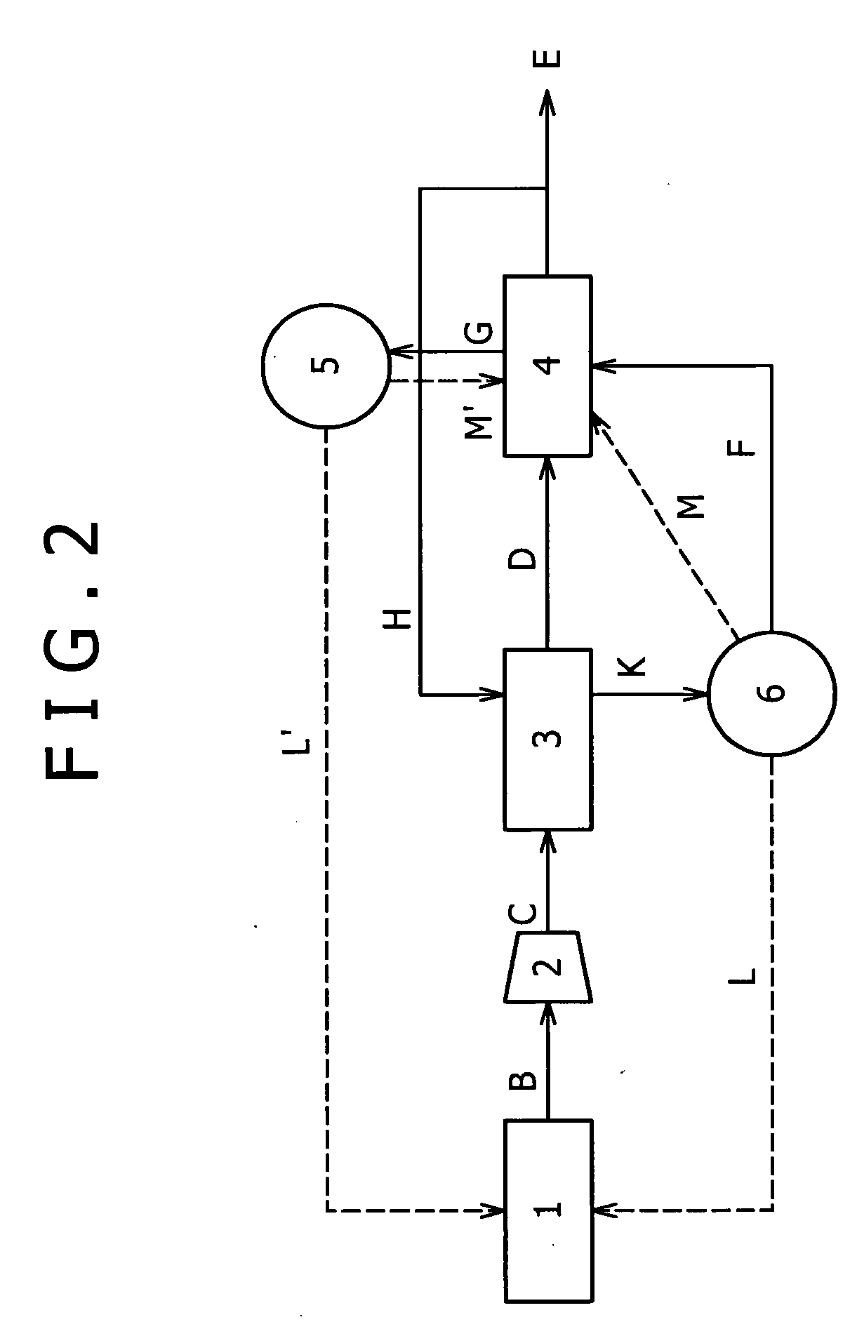
[0117]Another embodiment is shown in FIG. 2. Embodiment 1 illustrates an embodiment in which the part F of high-purity hydrogen is initially circulated in the carbon monoxide remover 4 to regenerate the carbon monoxide adsorbent, and the offgas (carbon monoxide adsorption tower offgas) G thereof is circulated in the PSA unit 3 to regenerate the PSA adsorbent (FIG. 1). With reference to FIG. 2, Embodiment 2 illustrates an embodiment in which the order of circulation is changed; a part of high-purity hydrogen H is initially circulated in the PSA unit 3 to regenerate the PSA adsorbent; and an offgas (PSA tower offgas) K thereof is circulated in the carbon monoxide remover 4 to regenerate the carbon monoxide adsorbent. The hydrogen recovery can be prevented from lowering according to the present embodiment as in Embodiment 1, except for regenerating the carbon monoxide adsorbent using the PSA tower offgas K instead of the high-purity hydrogen E.

[0118]The PSA tower offgas K can be used a...

embodiment 3

[0120]Yet another embodiment is shown in FIG. 3. The present embodiment (Embodiment 3) illustrates an embodiment in which a part F of high-purity hydrogen is used for regenerating the PSA adsorbent as in Embodiment 2, but the regeneration of the carbon monoxide adsorbent is conducted by circulating a PSA tower offgas K as a regeneration primary cleaning gas F1 and another part of high-purity hydrogen E as a secondary purge gas F2 sequentially in the carbon monoxide adsorption tower.

[0121]According to Embodiment 3, a product hydrogen with a further higher purity can be obtained as compared with Embodiment 2. This is because the product hydrogen (high-purity hydrogen) E is used as a secondary purge gas F2, and, by carrying out finish cleaning with the high-purity hydrogen free from impurities, the carbon monoxide adsorbent can be further highly regenerated, although the entire hydrogen recovery is lowered.


PUM

PropertyMeasurementUnit
purityaaaaaaaaaa
adsorptionaaaaaaaaaa
concentrationaaaaaaaaaa

Abstract

For recovering hydrogen with a high recovery from a reformed gas and contributing to downsizing and cost reduction of facilities, a high-purity hydrogen E is obtained by reforming a reformable raw material A through a reforming unit 1 to yield a hydrogen-rich reformed gas B, compressing the hydrogen-rich reformed gas B with a compressor 2, allowing the compressed gas to pass through a PSA unit 3 to remove unnecessary gases other than carbon monoxide by adsorption, and allowing the resulting gas to pass through a carbon monoxide remover 4 packed with a carbon monoxide adsorbent supporting a copper halide to remove carbon monoxide by adsorption.

Description

TECHNICAL FIELD[0001]The present invention relates to a method of producing high-purity hydrogen which is used typically for proton conduction fuel cells such as phosphoric acid fuel cells and solid polymer fuel cells (proton exchange fuel cells). Specifically, it relates to a method of efficiently producing high-purity hydrogen, in which by-produced carbon monoxide, carbon dioxide, water, and unreacted methane are removed in the production of hydrogen as an energy source (fuel) for fuel cells.BACKGROUND ART[0002]Combined with measures against global warming, a departure from dependency of energy on crude oil has become a world-wide important issue, and efforts to yield practically usable fuel cells using hydrogen gas as an energy source are stepping up not only in European industrialized countries, where efforts for environmental protection have preceded, but also in the United states of America, and Japan and other Asian countries.[0003]A number of studies on methods of producing ...

Claims


Application Information

Patent Timeline
Patent Type & Authority Applications(United States)
IPC IPC(8): C01B3/02
CPCC01B3/56C01B2203/047C01B2203/043C01B2203/042
Inventor NAKAO, NOBORUYAMASHITA, TAKESHIFUJISAWA, AKITOSHIYURA, KEITA
Owner KOBE STEEL LTD
Learn More