Method of preparing a transmission electron microscope sample and a sample piece for a transmission electron microscope

a technology of transmission electron microscope and sample piece, which is applied in the direction of liquid/fluent solid measurement, instruments, machines/engines, etc., can solve the problems of contamination on the surface of the sample piece, the finished surface cannot be processed, and the finished surface is difficult to process, etc., to achieve the effect of increasing productivity

Active Publication Date: 2009-05-07
HITACHI HIGH TECH SCI CORP
View PDF17 Cites 16 Cited by
  • Summary
  • Abstract
  • Description
  • Claims
  • Application Information

AI Technical Summary

Benefits of technology

[0020]The sample piece for a transmission electron microscope according to the present invention has an action and an effect similar to those in the above-mentioned case of Claim 2.
[0021]In the method of preparing a transmission electron microscope sample using the charged particle beam and the sample piece obtained as a result of the preparation method according to the present invention, when the sample piece is irradiated with the charged particle beam to be detached from th

Problems solved by technology

However, the method of preparing a transmission electron microscope sample described in Patent Document 1 has a problem in that the finished surface can not be processed with the sample piece being coupled to the sample body.
Specifically, if the finished surface is processed with the sample piece being coupled to the sample body, contamination is generated on a surface of the sample piece under the influence of the charged particle beam used when the sample piece is detached from the sample body.
If a sample piece wi

Method used


Image

  • Method of preparing a transmission electron microscope sample and a sample piece for a transmission electron microscope
  • Method of preparing a transmission electron microscope sample and a sample piece for a transmission electron microscope
  • Method of preparing a transmission electron microscope sample and a sample piece for a transmission electron microscope

Examples


Embodiment Construction

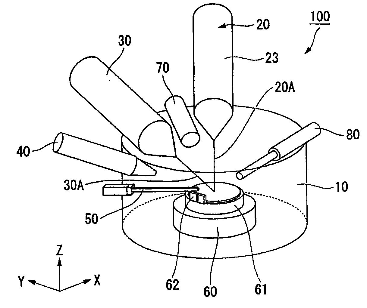
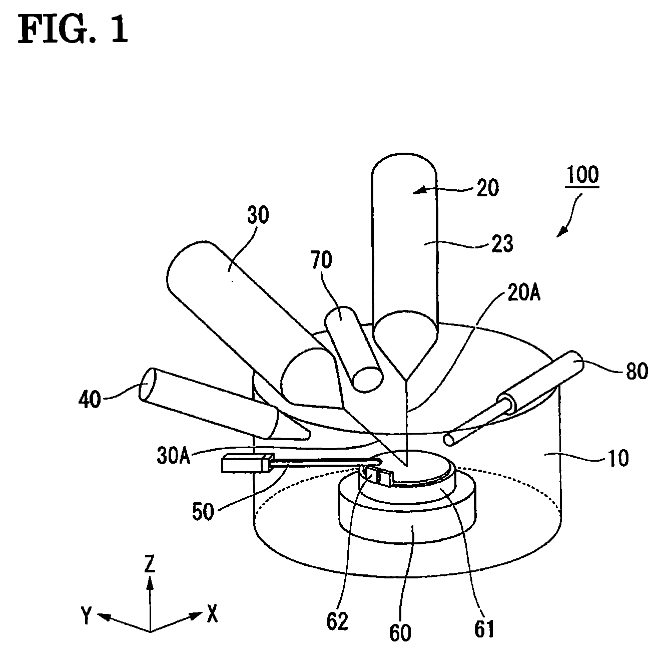
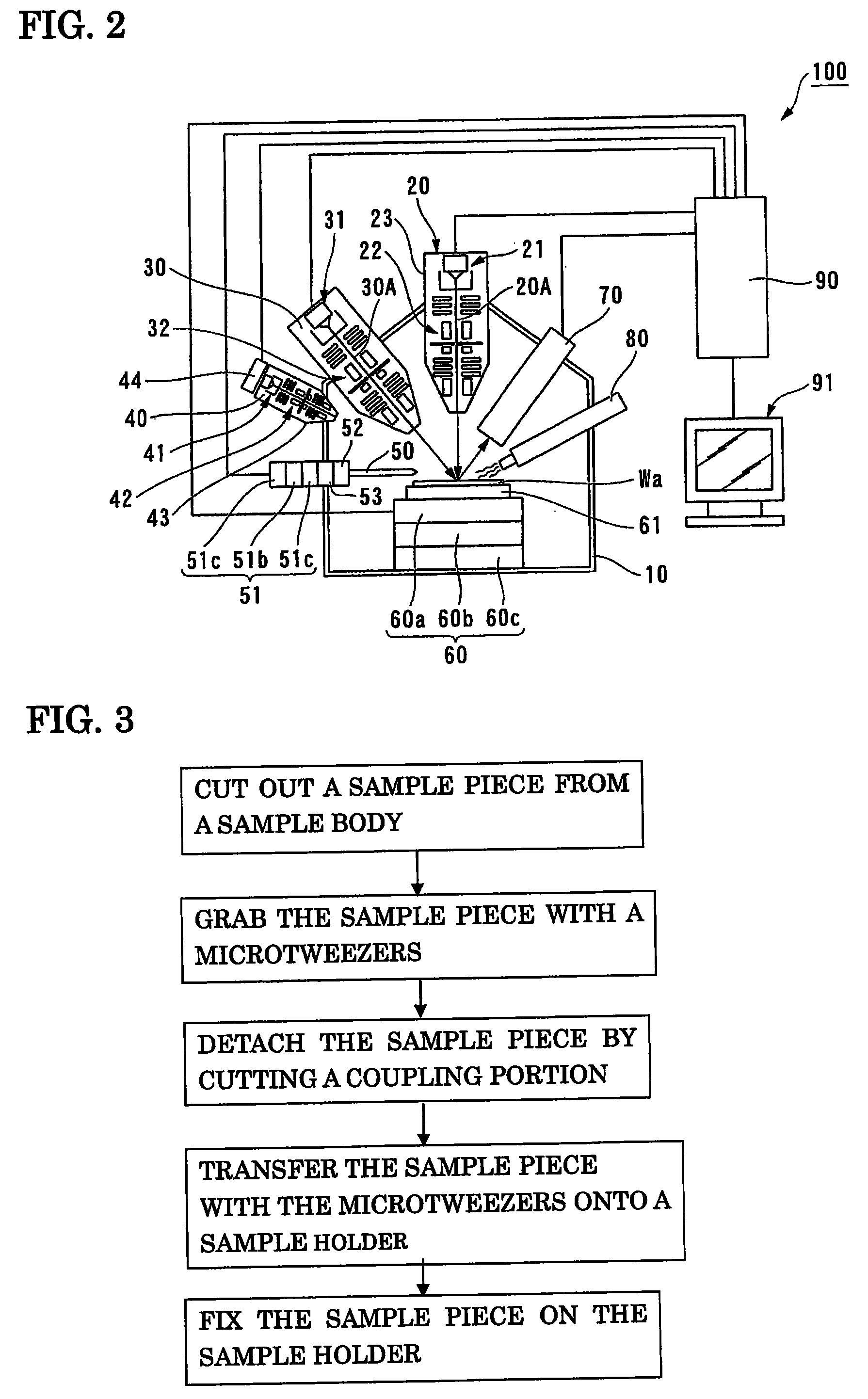
[0040]An embodiment of a method of preparing a transmission electron microscope sample according to the present invention is described in the following with reference to the drawings. Before describing the method of preparing a transmission electron microscope sample according to the present invention, a charged particle beam system directly used in carrying out the method is described. FIG. 1 is a schematic perspective view of a charged particle beam system 100. FIG. 2 is a schematic sectional view of the charged particle beam system 100.

[0041]As illustrated in FIG. 1 and FIG. 2, the charged particle beam system 100 includes a vacuum chamber 10, an ion beam irradiation system 20, an electron beam irradiation system 30, an argon ion beam irradiation system 40, nanotweezers 50 (microtweezers), a sample stage 60, a secondary charged particle detector 70, and a gas gun 80. The pressure in the vacuum chamber 10 can be reduced to a predetermined vacuum. All of the above-mentioned compone...


PUM


Abstract

Provided is a method of preparing a sample piece for a transmission electron microscope, the sample piece for a transmission electron microscope including a substantially planar finished surface which can be observed with the transmission electron microscope and a grabbing portion which microtweezers can grab without contacting the finished surface. The method of preparing a sample piece for a transmission electron microscope is characterized by including: a first step of cutting out the sample piece from a sample body Wa with a charged particle beam, the sample piece being coupled to the sample body at a coupling portion; a second step of grabbing with the microtweezers the grabbing portion of the sample piece with the finished surface of the sample piece cut out in the first step being covered with the microtweezers; a third step of detaching the sample piece grabbed with the microtweezers in the second step from the sample body by cutting the coupling portion with the charged particle beam with a grabbed state of the sample piece being maintained; and a fourth step of transferring and fixing with the microtweezers the sample piece detached in the third step onto a sample holder.

Description

RELATED APPLICATIONS[0001]This application claims priority under 35 U.S.C. §119 to Japanese Patent Application Nos. JP2007-288292 filed on Nov. 6, 2007 and JP2008-270964 filed on Oct. 21, 2008, the entire contents of which are hereby incorporated by reference.BACKGROUND OF THE INVENTION[0002]The present invention relates to a method of preparing a transmission electron microscope sample using a charged particle beam and a sample piece for a transmission electron microscope obtained as a result of the preparation method.[0003]Conventionally, for the purpose of observing a sample with a transmission electron microscope (TEM), a sample piece for a transmission electron microscope (hereinafter, simply referred to as sample piece) is prepared using a focused ion beam (FIB, a kind of charged particle beam) system (see, for example, JP 2006-120391 A).[0004]In a conventional sample preparation method using a focused ion beam system, a sample piece is first cut out from an original sample bo...

Claims


Application Information

Patent Timeline
IPC IPC(8): G01N13/10G01Q30/20
CPCB82Y15/00G01N1/286H01J37/20H01J37/26H01J37/3056H01J2237/2007H01J2237/202H01J2237/204H01J2237/206H01J2237/2067H01J2237/2802H01J2237/31745H01J2237/31749
Inventor MAN, XINIWASAKI, KOUJIASAHATA, TATSUYA
Owner HITACHI HIGH TECH SCI CORP
Why Eureka
Try Eureka