Method for enhanced synthesis of carbon nanostructures

a carbon nanostructure and carbon nanotube technology, applied in the direction of carbonsing rags, metal/metal-oxide/metal-hydroxide catalysts, physical/chemical process catalysts, etc., can solve the problem of not having the quantity and form of carbon nanotubes and carbon nanofibers that are needed for practical applications, and achieve the effect of improving the yield of carbon nanotubes and nanofibers

Inactive Publication Date: 2009-05-28
THE BOARD OF TRUSTEES OF THE UNIV OF ARKANSAS
View PDF4 Cites 47 Cited by
  • Summary
  • Abstract
  • Description
  • Claims
  • Application Information

AI Technical Summary

Problems solved by technology

However, the availability of CNTs and carbon nanofibers in quantities and forms necessary for practical applications is still problematic.

Method used


Image

  • Method for enhanced synthesis of carbon nanostructures
  • Method for enhanced synthesis of carbon nanostructures
  • Method for enhanced synthesis of carbon nanostructures

Examples


example 1

Growth and Harvest of SWNTs

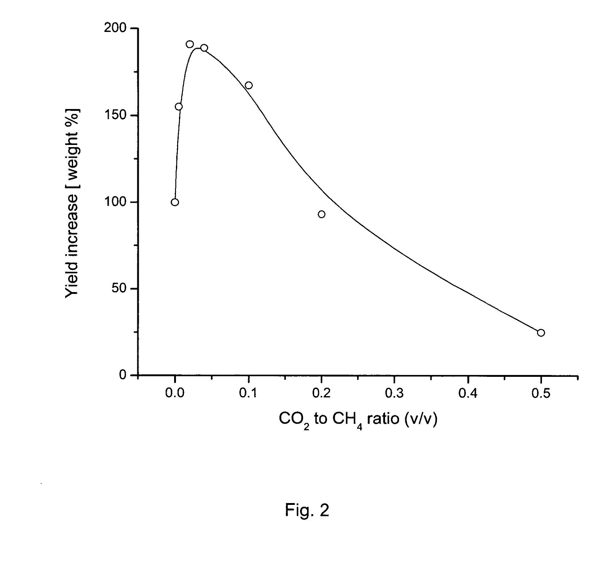
[0038]Catalyst Preparation. Any catalyst known to those in the art can be used in the practice of the present invention. One such example is the following: A Fe—Mo / MgO catalyst was prepared by an impregnation method. An iron nitrate hydrate (Fe(NO3)3.9H2O) and ammonium molybdate ((NH4)6Mo7O24.4H2O) solution with MgO powder was ultrasonicated to a gel, dried at 383 K, ground to a fine powder, and then calcined at 823 K. The weight ratio of catalyst was 1:1:40 for Fe / Mo / MgO.

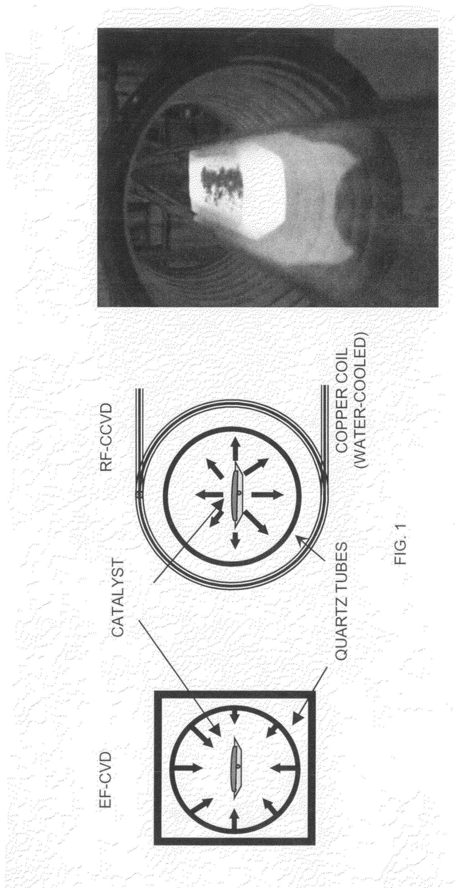
[0039]Synthesis of SWNTs. The synthesis of SWNTs at 1173 K performed with adding and not adding CO2 were compared. Around 200 mg of the catalyst was uniformly spread into a thin layer under nitrogen flow at 200 ml / min on a graphite susceptor and placed at the center of a quartz tube positioned horizontally inside an inductive furnace. After purging the system with nitrogen as carrier gas for 10 minutes, radio frequency (RF) heating at 350 KHz was applied to the graphite susceptor that con...

example 2

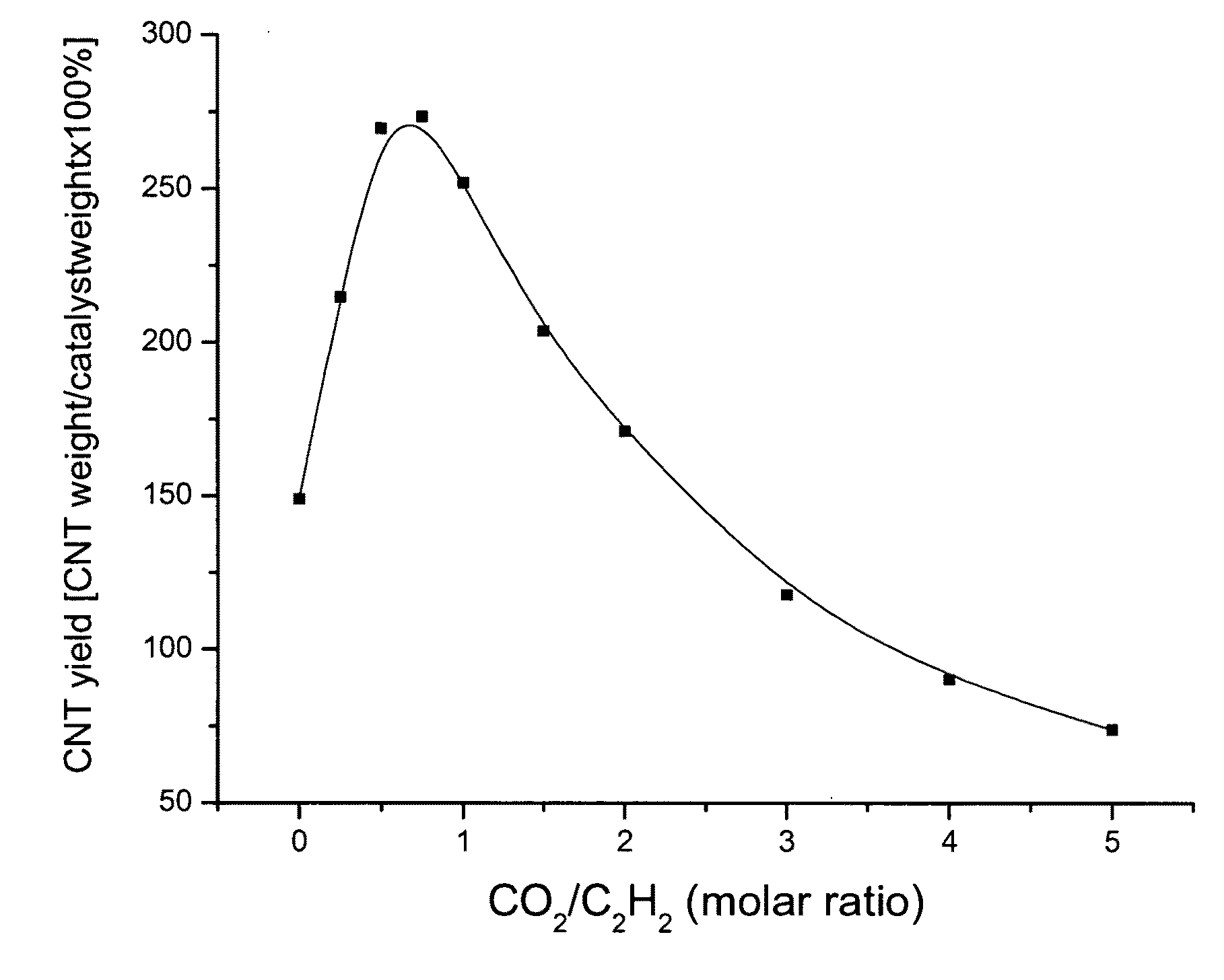
(A) Growth of MWNTs on Fe—Co / CaCO3 Catalysts

[0051]Fe—Co / CaCO3 catalysts. The stoichiometric composition of the catalyst was Fe:Co:CaCO3=2.5:2.5:95 wt %. First, the weighted amount of metal salts Fe(NO3)3.9H2O and Co(CH3COO)2.4H2O were dissolved into distilled water with agitation, and CaCO3 was added to the solution after the metal salts were completely dissolved. The pH-value of the mixture solution was adjusted to about 7.5 by dripping ammonia solution, in order to avoid the release of CO2 occurring when carbonates contact acids. Then, the water was evaporated with a steam bath under continuous agitation, and the catalyst was further dried at about 130° C. overnight.

[0052]Carbon nanotubes were synthesized on the Fe—Co / CaCO3 catalyst with cCVD approach using acetylene as carbon source. About 100 mg of the catalyst was uniformly spread into a thin layer on a graphite susceptor and placed in the center of a quartz tube with inner diameter of 1 inch, which is positioned horizontally i...


PUM

PropertyMeasurementUnit
temperatureaaaaaaaaaa

Abstract

A method of significantly improving carbon nanotube or carbon nanofiber yield from catalytic chemical vapor deposition of a carbon-containing gas comprising at least one hydrocarbon with the assistance of a proper amount of carbon dioxide (CO2). The catalytic particles preferably contain at least one metal from Group VIII (Fe, Co, Ni or the like) or / and one metal from Group VIb, including Mo, W, and Cr. The catalytic particles are preferably supported on oxide powders such as MgO, Al2O3, SiO, CaO, TiO, and ZrO, or a flat substrate such as, but not limited to, a Si wafer. The carbon nanotube or nanofiber product is preferably formed by exposing the catalyst to a mixture of a carbon-containing gas comprising at least one hydrocarbon with a proper amount of CO2 at a sufficiently high temperature. In an alternative embodiment, other oxygen-containing gases, such as alcohols, may be included in the mixture in addition to carbon dioxide.

Description

CROSS-REFERENCE TO RELATED APPLICATIONS[0001]This application claims the benefit of U.S. Provisional Patent Application No. 61 / 003,206 filed Nov. 15, 2007, the disclosure of which is incorporated herein by reference in its entirety.STATEMENT REGARDING FEDERALLY SPONSORED RESEARCH OR DEVELOPMENT[0002]Not applicable.BACKGROUND OF THE INVENTION[0003]This invention is related to the field of catalysis for producing carbon nanostructures, including carbon nanotubes and nanofibers.[0004]Carbon nanotubes (CNTs) are seamless tubes of graphite sheets with full fullerene caps which were first discovered as multi-layer concentric tubes or multi-walled carbon nanotubes (MWNTs) and subsequently as single-walled carbon nanotubes (SWNTs) formed in the presence of transition metal catalysts. Carbon nanotubes have shown promising applications including nanoscale electronic devices, high strength materials, electron field emission, tips for scanning probe microscopy, solar cell, and gas storage.[0005...

Claims


Application Information

Patent Timeline
Patent Type & Authority Applications(United States)
IPC IPC(8): D01F9/127B82B3/00
CPCB01J21/10B01J23/75B01J23/78B01J23/881B01J23/8872B01J27/232D01F9/127B82Y40/00C01B31/0233C01B2202/02C01B2202/04C01B2202/06C01P2004/133B82Y30/00C01B32/162
Inventor LI, ZHONGRUIXU, YANGBIRIS, ALEXANDRU S.
Owner THE BOARD OF TRUSTEES OF THE UNIV OF ARKANSAS
Why Eureka
Try Eureka