Method of Assessing Bond Integrity in Bonded Structures

a bond integrity and bonding technology, applied in the direction of material analysis, instrumentation, and solid analysis using sonic/ultrasonic/infrasonic waves, can solve the problems of poor bond integrity, poor bond integrity, and few techniques that can be applied to honeycomb or foam core-structured materials, etc., to achieve a thorough and reliable inspection

Inactive Publication Date: 2009-07-02
NAT RES COUNCIL OF CANADA
View PDF2 Cites 39 Cited by
  • Summary
  • Abstract
  • Description
  • Claims
  • Application Information

AI Technical Summary

Benefits of technology

[0016]The material may be a layered and / or composite bonded structure, for example, a honeycomb structure, a structure with a foam core, a coating on a solid, a laminate etc. On honeycomb structures and on foam core structures, if a sufficiently short generation pulse is used, the approach can also exploit ultrasonic waves that are generated through the membrane to get a more thorough and reliable inspection by distinguishing delaminations within the skin from detachments of the skin from the ribs. Furthermore, on laminates and in structured materials that may develop disbonds at different depths, the use of a short pulse allows for determination of a depth of the disbond using a time between the reverberating ultrasonic echoes. Thus, the present method is particularly useful for analyzing honeycomb and foam core structures.

Problems solved by technology

Voids or detachments at the coating-substrate interface result in a fragile coating that could become detached, leaving the substrate unprotected and subjected to severe heat load, erosion, oxidation or corrosion.
Very few techniques are known that can be applied to honeycomb or foam core-structured materials, particularly if the structure can only be interrogated from only one side.
Difficulties arise because of limitations of penetration of acoustic and thermal waves through the bonded structure, and consequently there is very little change of properties, such as acoustic reflection or thermal conductivity, between a good bond and lack of bond.
Most of the techniques that have been developed to test bond integrity of coatings and the integrity of laminates from single side access cannot be applied reliably to honeycomb or foam core structured materials.
This technique, which requires access to both sides of the material, is possible at fabrication but usually not possible while assembled in a structure (such as in an airplane wing).
Therefore all the existing ultrasonic techniques that require either contact or water coupling or non contact as in laser-ultrasonics have important limitations.
This is because each speckle of light returning from the surface effectively is a separate beam having its own respective random phase offset and random amplitude, and consequently, if multiple speckles are gathered for use in such an interferometer, each pair of beams (speckles as well as the reference beam) produces a separate interference pattern, all of which interference patterns are superimposed, resulting in a sharply reduced sensitivity of the measurement.
Accordingly, scanning a part to get an image of the adhesion integrity of the structured material is not very practical.
It would be unpractical and too onerous to apply a special coating or paint which has a sufficiently smooth surface to give speckle-free reflection.

Method used


Image

  • Method of Assessing Bond Integrity in Bonded Structures
  • Method of Assessing Bond Integrity in Bonded Structures
  • Method of Assessing Bond Integrity in Bonded Structures

Examples


example 1

Honeycomb Carbon Epoxy Test Sample

[0082]Example 1 is an application to a carbon epoxy honeycomb structure with artificially produced delaminations in the skin, and skin-core detachments. A schematic illustration of the location of the defects is shown in FIG. 4, and a picture of the test sample is shown in FIG. 5.

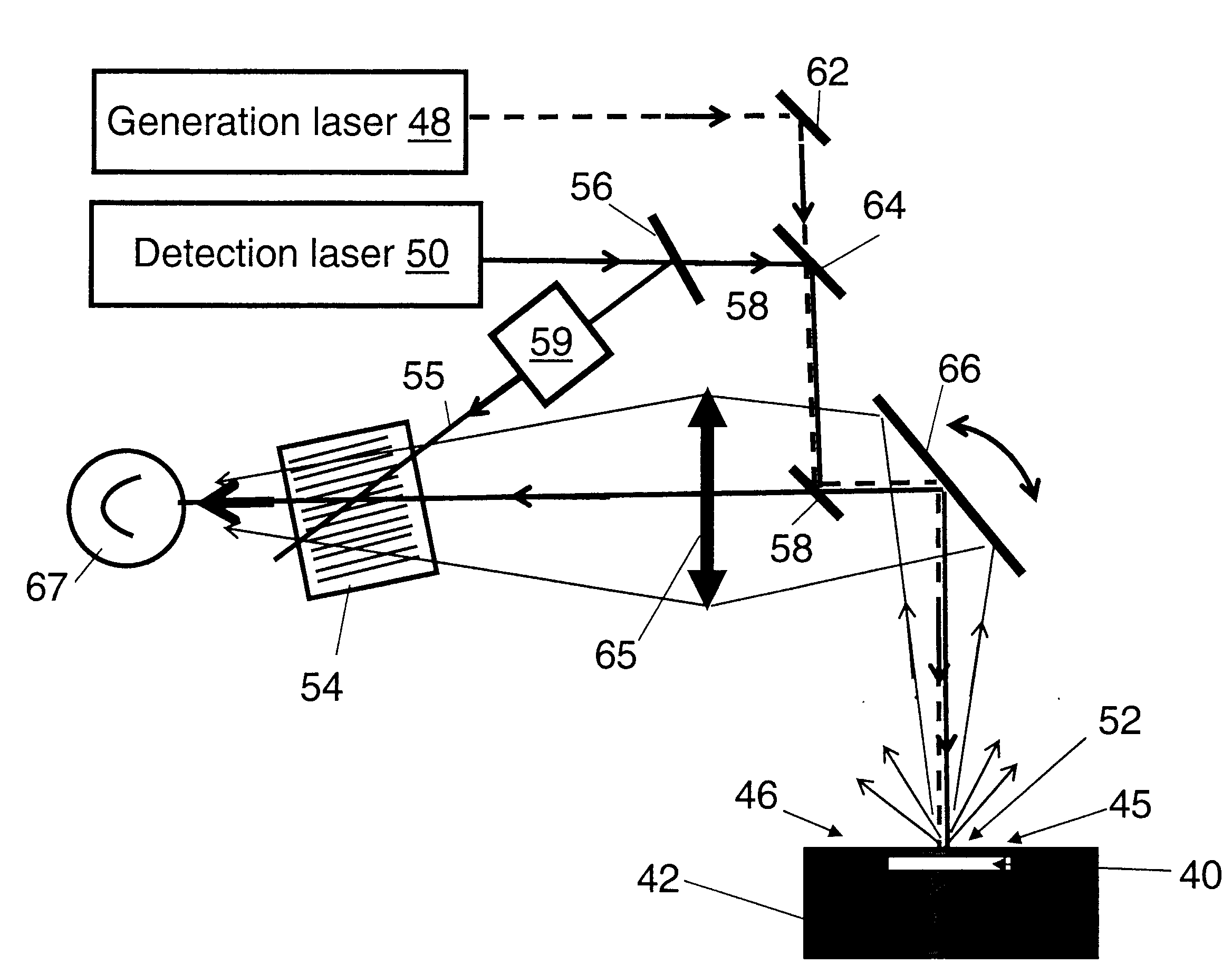
[0083]The experimental setup as shown in FIG. 3a is used. The generation laser employed is a CO2 TEA laser which delivers pulses of about 100 mJ energy and 120 ns duration at 10.6 μm wavelength makes the detached area lift up and vibrate like a membrane clamped at its edges. It also generates ultrasonic waves. The excitation mechanism in this case is purely thermoelastic, and non-damaging. The detection laser is a pulsed single frequency Nd:YAG laser which delivers pulses of about 50 mJ energy and 65 μs duration at 1.064 μm wavelength, and the laser detects both the vibration and ultrasound echoes. The detection laser light scattered off the surface of the inspected part is...

example 2

Anti-Wear Tungsten Carbide-Cobalt Coating on Steel

[0093]With reference to FIGS. 12 and 13, example 2 demonstrates the detection of detachment of a Tungsten Carbide-Cobalt (WC—Co) coating on steel, although the technique is applicable to the detection of disbonds between an exposed first layer overlying a second material in general. These coatings are currently developed for replacing hard chromium coatings, which are at the source of known environmental problems. They are used on parts such as aircraft landing gears. These parts are subjected to fatigue cracking. Fatigue cracks may lead to detachment between the coating and the substrate, which are likely to follow by complete coating peel-off leaving the substrate unprotected from corrosion. Therefore the detection of such disbonds is very important.

[0094]In this case, the generation spot and the detection spot were slightly offset by about a spot size. In FIG. 12 one observes the arrival of a surface wave followed by a featureless...

example 3

Silicon Carbide Protecting Layer on a Carbon-Carbon Substrate

[0095]Example 3 shows the detection of detachments occurring between a SiC oxidation protecting layer and a C—C substrate. Carbon-carbon substrates are widely used as thermal shields in rocket engines and on fuselages of space vehicles, such as the U.S. space shuttle. Since carbon is prone to reaction with oxygen above 450° C., C—C materials are generally protected by a ceramic coating such as one made of silicon carbide. The coating being porous, with time voids are produced by oxidation. If these voids grow bigger, the coating could get detached leaving the C—C substrate unprotected and subjected to severe oxidation. Therefore, the detection of disbonds between the coating and the C—C substrate is important.

[0096]These coatings are however porous and strongly attenuate ultrasound, so pulse-echo ultrasonics does not work. Actually this approach was tried on the C—C sample used and no echo was observed. However, with the t...


PUM


Abstract

A technique for acoustic detection of a disbond within a bonded structure involves thermal excitation of the surface of the bonded structure to induce a lifting and membrane vibration and is applicable to laminates and coated structures, as well as foam core structures or a honeycomb structures. The technique does not require access to both sides of the bonded structure. A large etendue interferometer is used to provide surface displacement measurement. The surface displacement measurement can be analyzed both by frequency or amplitude to determine existence of a disbond by membrane vibration, and further a thickness of the disbond can be determined using traditional pulse-echo time analysis. The technique may allow detection of stick bonds.

Description

FIELD OF THE INVENTION[0001]The present invention relates in general to nondestructive testing of bonded structures, and in particular to a laser thermo-acoustic technique for assessing bond integrity.BACKGROUND OF THE INVENTION[0002]There are many bonded materials deployed in structural arrangements wherein the structural utility of the bonded material depends on a bond quality of the bonded material. In applications where the structural arrangements are critical, there is a need to evaluate the bond quality.[0003]Honeycomb-structured materials allow fabrication of structures having reduced weight while keeping a very high stiffness. Such materials are particularly useful in the aeronautics and space industry. Honeycomb structured materials typically have two skins, and a core layer of ribs extending perpendicular to the skins to form hexagonal cells. The skins are usually laminates, such as e.g. carbon-epoxy laminates made of layers of carbon fibers in an epoxy resin. Two kinds of...

Claims


Application Information

Patent Timeline
Patent Type & Authority Applications(United States)
IPC IPC(8): G01B11/02G01B9/02
CPCG01N21/1702G01N29/2418G01N2291/0423G01N2291/0231G01N29/265
Inventor MONCHALIN, JEAN-PIERREBLOUIN, ALAINCAMPAGNE, BENJAMIN
Owner NAT RES COUNCIL OF CANADA
Why Eureka
Try Eureka