Implantable biomimetic prosthetic bone

a biomimetic and prosthetic bone technology, applied in the field of implantable biomimetic composite prosthetic materials, can solve the problems of aseptic loosening, pain to the host, and clear inability to retrieve thp

Inactive Publication Date: 2009-07-09
NAT RES COUNCIL OF CANADA
View PDF17 Cites 159 Cited by
  • Summary
  • Abstract
  • Description
  • Claims
  • Application Information

AI Technical Summary

Benefits of technology

[0019]It is an object of the present invention to obviate or mitigate at least one disadvantage of previous prosthetic bones, or methods for their formation.
[0024]Advantageously, embodiments of the inventive prosthetic bone can match the bone density (specific weight) and structure of the bone to which the prosthetic bone will become adjacent upon implantation.
[0025]As a further advantage, the problem of stress shielding can be in part or wholly overcome with embodiments of the invention that allow for a close stiffness (elastic modulus) match between the materials of the prosthetic bone and the bone to which the prosthetic bone will become adjacent upon implantation.
[0026]The presence of an internal core in embodiments of the prosthetic bone of the instant invention advantageously reduces the risk of buckling, as may be found in such prosthetic bone materials that do not include internal cores.

Problems solved by technology

While this could be acceptable for older, less active patients, this retrieval rate of THP is clearly not appropriate for younger patients, for which considerably longer implantation periods are required.
The main problem with presently used THPs lies in a phenomenon known as aseptic loosening, which is attributed to a stiffness mismatch between the bone and the implant.
One cause of this phenomenon is stress shielding, while but formation of wear debris is also widely reported as a contributor to this problem.
This eventually generates an inflammatory response of the body causing pain to the host and requiring removal of the implant.
When replaced, metallic stems of THPs need to be inserted deeper into the femoral bone, which makes it progressively weaker and increases the risk of fracture.
In addition to bone weakening, the metal of the stem may suffer corrosion fatigue and can cause adverse tissue reactions.
Such implants, however, are susceptible to fatigue and debris formation and do not eliminate the problem of stress shielding and the associated bone resorbtion.
However, this approach does not address the need for matching by the stem the bone stiffness, density and structure, and does not eliminate the problem of stress shielding.
This approach does not address the need for the stem to match bone density and structure.
As the bone modulus match is limited to in-plane stiffness components, the moduli normal to the laminate structure cannot be modulated, which does not eliminate completely the stress shielding.
While addressing the problem of stress shielding, this approach does not address the need for matching by the stem the bone density and structure.
The molding process is very complex and expensive, because the process requires very high compaction pressures.
Controlling the orientation of the composite sheath is problematic.
This approach does not address the need for the stem to match the bone stiffness, density and structure, and the problem of eliminating the stress shielding is not explicitly addressed.
However, this design does not address the need for the stem to match the bone stiffness, density and structure.
While the stiffness of the stem can be varied in this design, the range of such adjustments is fairly limited due to its longitudinally fibre reinforced polymer core and there is no explicit mention of providing a solution to the problem of stress shielding.
As for earlier discussed designs, this design does not address the need for the stem to match the bone stiffness, density and structure.
While the stiffness of the stem can be varied in this design, the range of such adjustments is fairly limited, to values above the range of femoral bone moduli, due to the longitudinally fibre reinforced polymer core.
While matching the modulus of the bone and the material at surface of the stem is considered, the overall bone modulus cannot be matched using this design, nor can the bone density and structure.
While the modulus of the stem surface material can be varied in this design, the range of stiffness that can be obtained from the stem is considerably above the range of femoral bone stiffness due to the longitudinally fibre reinforced polymer core and there is no explicit mention of providing a solution to the stress shielding.
While a large range of mechanical characteristics with a good rigidity / dimension ratio can be obtained for the stem using this design, such a design does not consider the need for the stem material to match the bone modulus, density and structure.
The design also does not include an internal core, which considerably increases the risk of buckling of the stem.
While admitting that the bone adjacent to the stem is subjected to flexural stresses similar to those experienced when a metallic stem is used, this design does not address the problem of stress shielding.
This design does not address the need for the stem to match the bone stiffness, density and structure.
While the stiffness of the stem can be varied in this design, the range that can be obtained is not explicitly disclosed and there is no explicit mention of providing a solution to the problem of stress shielding.
This design also does not include an internal core into the stem structure, which raises considerably the risk of stem buckling.

Method used


Image

  • Implantable biomimetic prosthetic bone
  • Implantable biomimetic prosthetic bone
  • Implantable biomimetic prosthetic bone

Examples


example 1

Total Hip Prosthesis (THP)

[0072]In this example, the inventive prosthetic bone according to the invention is a biomimetic THP stem.

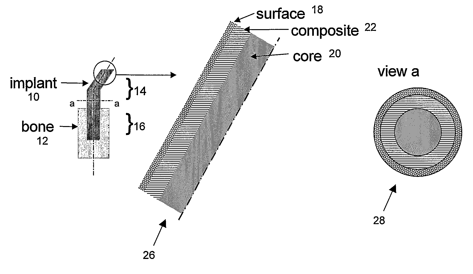
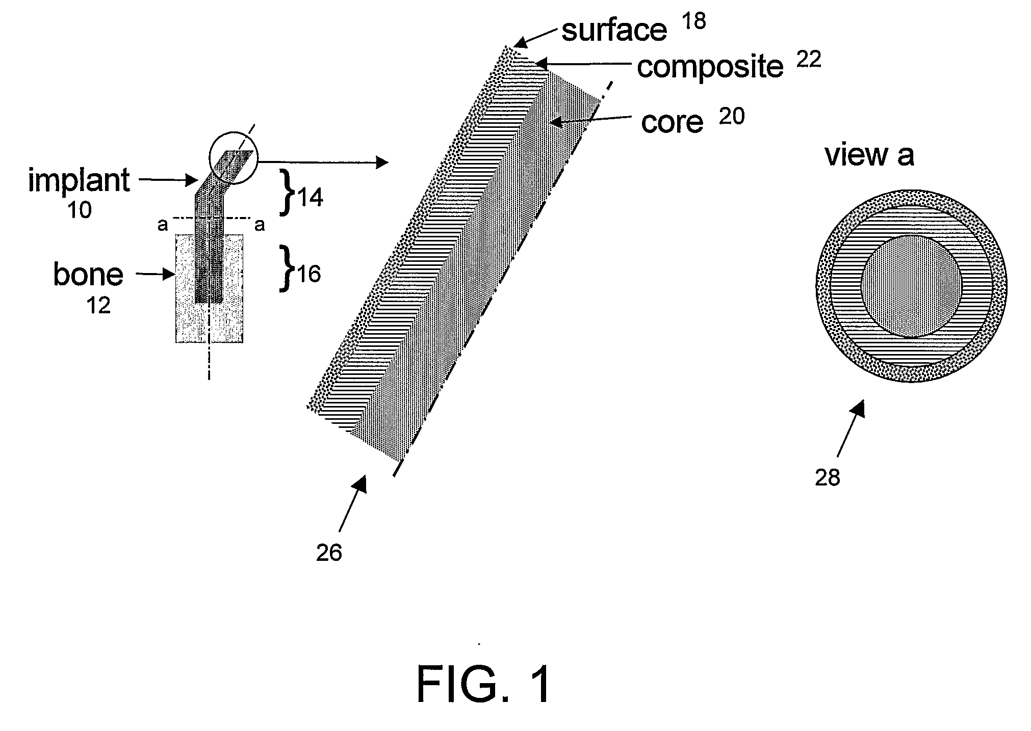
[0073]FIG. 1 illustrates a prosthetic bone according to the invention, in this case formed as a THP stem or “implant” (10) to be implanted in hip replacement surgery, to be inserted in the femoral bone (12). The stem has an extra-osseous end (14) and an intra-osseous end (16). The surface (18) of the implant is designed so that fixation of the implant to the host tissue, either by adhesive bonding or by bone integration, allows a good stress transfer between the implant (10) and the bone (12) at any point along the implant (stem). At any point along the stem, its stiffness adjacent to the bone approximately matches that of the bone, making stresses in the bone and the stem approximately equal in the vicinity of the bone-stem interface. Section a..a illustrates the 3 layers: polymer-based core (20), fiber-reinforced thermoplastic composite (22) and surfac...

example 2

Fiber-Reinforced Composite

[0076]To illustrate the bone-matching properties of the composite, a CF / PA12 composite having 68 wt % long carbon fibers and 32 wt % polyamide 12 was compression-molded in different lay-up configurations (fiber orientations) and tested for flexural and interlaminar resistance using standard testing methodology (ASTM D790 / D2344). The results showed that, depending on the molding configuration, the moduli obtained ranged between 8 and 36 GPa and the mechanical strengths between 134 and 565 MPa. Thus the moduli which were obtained for a THP stem made of these composites correspond to those reported for dense bones (5-30 GPa). At the same time, the mechanical strength of these composite stems proved to be significantly above that of dense bones (100-200 MPa), showing that in extreme physiological conditions the composite stems of the invention would be subjected to stresses considerably below those leading to their failure. The latter property is advantageous b...

example 3

Bioactive HA Coating

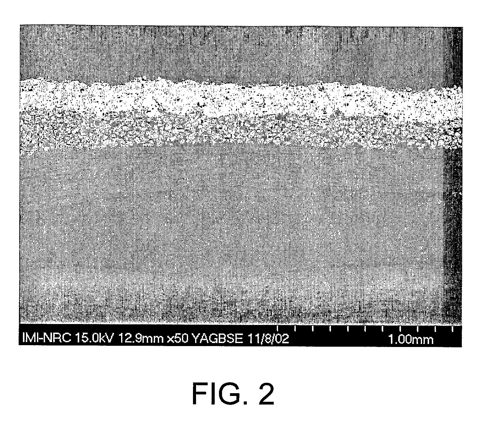
[0078]To evaluate the feasibility of HA coatings of acceptable adhesion on the composite stems of the invention, flat coupons of CF / PA12 composite were prepared and coated by plasma spraying.

[0079]FIG. 2 illustrates an exemplary surface of HA coating on a CF / PA12 composite with a film interlayer. The film interlayer is composed of 25% vol. in HA particles (mean diameter of 30 μm) in a PA12 matrix. This layer was obtained by incorporating HA particles in a PA12 matrix using a twin screw extruder (TSE) and pelletizing the PA12 / HA compound. Then a 200-300 μm-thick film was produced from the pellets of this compound using a cast film line extruder. A composition of 25% (v / v) HA / PA12 for the compound was used. The film was then overmolded on the CF / PA12 composite cylindrical structures by inflatable bladder molding in a closed mold placed into a heated press. The resulting part was then coated with HA using plasma spray.

[0080]Results showed that an HA-filled polymer f...


PUM

PropertyMeasurementUnit
porosityaaaaaaaaaa
roughnessaaaaaaaaaa
roughnessaaaaaaaaaa

Abstract

Bone tissue at the interface of a bone implant is shielded from stresses found in normal bone because of the higher stiffness or rigidity in the implant versus in bone. The resulting “stress shielding” of the bone by the implant eventually results in resorption of bone at the bone-implant interface and ultimately necessitates replacement of the bone implant. To overcome these problems, an implantable biomimetic prosthetic bone having a porous surface, a fiber-reinforced composite structure, and a polymer-based core is disclosed. The prosthetic bone is a good match for structure, stiffness, viscoelastic properties, specific weight and overall structure as real bone or host tissues adjacent to the prosthetic bone. The prosthetic bone may be formed as a total hip prosthesis.

Description

CROSS REFERENCE TO RELATED APPLICATIONS[0001]This application claims the benefit of priority of U.S. Provisional Patent Applications No. 60 / 643,599 filed Jan. 14, 2005, and No. 60 / 676,299 filed May 2, 2005, each of which is incorporated herein by reference.FIELD OF THE INVENTION[0002]The present invention relates generally to implantable prosthetic materials, in particular to biomimetic composite prosthetic materials and prostheses made of such materials.BACKGROUND OF THE INVENTION[0003]Metallic prosthetic implants have enjoyed enormous success for replacing bone and for bone fracture fixations and repairs. Among those, the Charnley-type hip replacement implant became an orthopedic success story as the second most frequently performed surgical procedure after the appendix ablation.[0004]The hip joint is a ball-and-socket joint in which the spherical head of the thighbone (femur) moves inside the cup-shaped hollow socket (acetabulum) of the pelvis. To duplicate this action, a total h...

Claims


Application Information

Patent Timeline
Patent Type & Authority Applications(United States)
IPC IPC(8): A61F2/28B29C70/00B29C43/02
CPCA61L27/446Y10T428/25B29C43/003B29C70/025B29C70/58B29C70/64B29K2503/04B29K2705/00B29K2709/00B29L2031/7532C08J5/124C08K3/0033C23C4/10C23C4/12C23C4/127Y02T50/67Y10T428/26A61L27/46C23C4/134C08K3/013Y10T428/31507Y10T428/31678Y10T428/31721Y10T428/31725Y10T428/31855Y02T50/60
Inventor BUREAU, MARTIN N.LEGOUX, JEAN-GABRIELDENAULT, JOHANNE
Owner NAT RES COUNCIL OF CANADA
Why Eureka
Try Eureka