Fuel cell anode structure for voltage reversal tolerance

a fuel cell and voltage reversal technology, applied in the field of anodes, can solve the problems of voltage reversal, voltage reversal in a pem fuel cell, voltage reversal, platinum-sensitive catalysts,

Active Publication Date: 2009-07-23
BDF IP HLDG
View PDF40 Cites 29 Cited by
  • Summary
  • Abstract
  • Description
  • Claims
  • Application Information

AI Technical Summary

Benefits of technology

[0017]In brief, an electrode assembly for a fuel cell is provided, the electrode assembly comprising an electrolyte interposed between an anode and cathode, a cathode catalyst layer interposed between the electrolyte and the cathode, and an anode catalyst layer interposed between the electrolyte and the anode. The anode layer comprises a first catalyst composition comprising a noble metal, other than Ru, on a corrosion resistant support material; a second catalyst composition consisting essentially of a single-phase solid solution of a metal oxide containing Ru; and a hydrophobic binder, and wherein a through-plane concentration of an ionomer in the catalyst layer decreases as a function of distance from the electrolyte.

Problems solved by technology

PEM fuel cells typically employ noble metal catalysts, and it is well known that such catalysts, particularly platinum, are very sensitive to carbon monoxide poisoning.
Voltage reversal occurs when a fuel cell in a series stack cannot generate sufficient current to keep up with the rest of the cells in the series stack.
Several conditions can lead to voltage reversal in a PEM fuel cell, for example, including insufficient oxidant, insufficient fuel, insufficient water, low or high cell temperatures, and certain problems with cell components or construction.
Aside from the loss of power associated with one or more cells going into voltage reversal, this situation poses reliability concerns.
Undesirable electrochemical reactions may occur, which may detrimentally affect fuel cell components.
Component degradation reduces the reliability and performance of the affected fuel cell, and in turn, its associated stack and array.
However, Ru has been shown to be unstable under certain fuel cell operating conditions.

Method used


Image

  • Fuel cell anode structure for voltage reversal tolerance
  • Fuel cell anode structure for voltage reversal tolerance
  • Fuel cell anode structure for voltage reversal tolerance

Examples


example 1

CO Stripping Cyclic Voltammetry

[0107]The cathode performance of a fuel cell incorporating an embodiment of the present anode was tested by CO stripping CV. Sample 11 was identical to Sample 1, described above, except that the anode catalyst contained an 4.5:1 admixture of 50% Pt supported on graphitized carbon black (TKK, Tokyo, JP) and unsupported RuIrO2 (single-phase solid solution (90:10 mole ratio Ru / Ir); Johnson Matthey Plc, London, UK), at a catalyst loading of ˜0.25-0.35 mg Pt / cm2 and ˜0.16-0.17 mg RuIrO2 / cm2. The same CO stripping CV procedure was used as described for Samples 1 and 2.

[0108]The resulting cathode voltammogram for Sample 11 is illustrated in FIG. 10. A comparison of the cathode CO peak at the beginning of the test (A) and the end of the test (B) shows no significant change in oxygen reduction kinetics, indicating no Ru contamination of the cathode catalyst layer. This is consistent with the presence of single phase crystal (rutile) RuIrO2, which has been shown...

example 2

Reversal Tolerance Testing

[0109]The testing of Samples 7-10 clearly demonstrates the unexpected and significant negative impact of the presence of amorphous Ru oxides on MEA cell reversal tolerance. Further cell reversal tolerance testing was performed to demonstrate the impact of the presence or absence of ionomer in the anode catalyst layer mixture.

[0110]MEA Samples 12-14 were assembled and tested using Ballard Mk 902 hardware under the operating conditions described for Samples 7-10, above. Sample 12, which incorporated an embodiment of the present anode, was compared to MEAs with anode catalyst layers comprising catalyst and ionomer. Samples 12-14 were prepared in a like manner to the MEAs described for FC-1-FC-4, above, except that:

[0111](1) the cathode catalyst layer comprised catalyst (50% Pt supported on graphitized carbon black (TKK, Tokyo, JP)) and ionomer (Nafion®) in a 2:1 ratio;

[0112](2) the anode catalyst comprised a 4.5:1 admixture of 50% Pt supported on graphitized c...

example 4

Start / Stop Cycle Testing

Stack FC-8 (EDH 564)

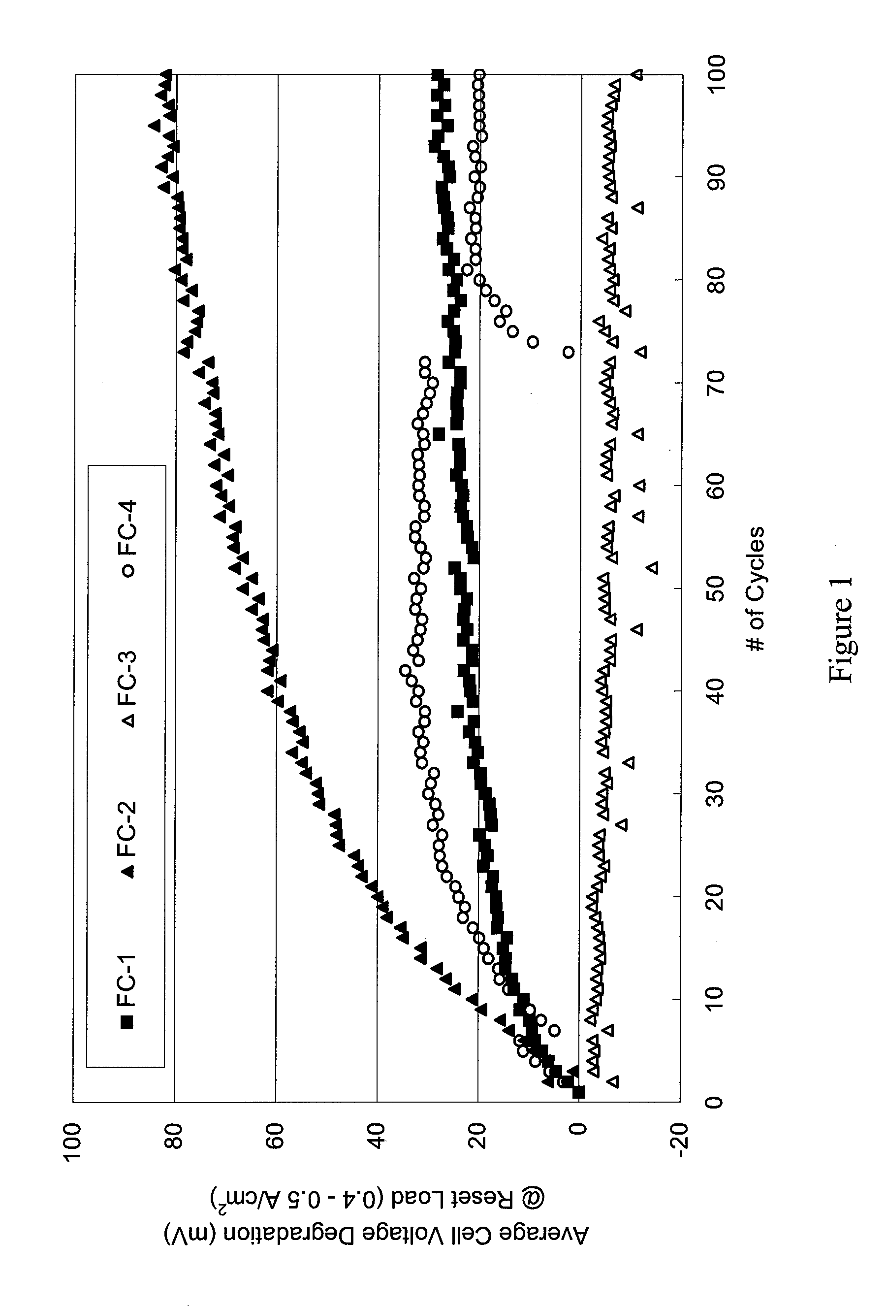
[0122]A further 20-cell Ballard Mk 1100 stack incorporating an embodiment of the present anode was assembled and subjected to start / stop cycle testing. FC-8 was assembled as described for stacks FC-1-FC-4, above, except that the anode catalyst contained an 4.5:1 admixture of 50% Pt supported on graphitized carbon black (TKK, Tokyo, JP) and unsupported RuIrO2 (single-phase solid solution (90:10 mole ratio Ru / Ir); Johnson Matthey Plc, London, UK), at a catalyst loading of 0.25-0.35 mg Pt / cm2 and 0.16-0.17 mg RuIrO2 / cm2. FC-5 was tested according to Duty Cycle 1, as described above.

[0123]FIG. 13 is a graph of the average cell voltage degradation as a function of start / stop cycles for fuel cell stack FC-8. The plots for FC-1-FC-4 from FIG. 1 have also been included for ease of comparison. As shown in FIG. 13, the voltage degradation for FC-8 was dramatically lower than the voltage degradation of FC-2, and was significantly improved over FC-1 o...


PUM

PropertyMeasurementUnit
output voltageaaaaaaaaaa
transient voltagesaaaaaaaaaa
corrosion resistantaaaaaaaaaa

Abstract

An anode catalyst layer for a fuel cell is presented having first and second catalyst compositions and a hydrophobic binder. The first catalyst composition includes a noble metal, other than Ru, on a corrosion-resistant support material; the second catalyst composition contains a single-phase solid solution of a metal oxide containing Ru. The through-plane concentration of ionomer in the catalyst layer decreases as a function of distance from the membrane interface. Gas diffusion electrodes, catalyst-coated membranes, MEAs and fuel cells having the foregoing anode catalyst layer are also described.

Description

BACKGROUND[0001]1. Technical Field[0002]The present invention relates to an anode for use in PEM fuel cells, and to fuel cells comprising said anode, having improved tolerance to voltage reversal.[0003]2. Description of the Related Art[0004]Fuel cell systems are currently being developed for use as power supplies in numerous applications, such as automobiles and stationary power plants. Such systems offer promise of delivering power economically and with environmental and other benefits. To be commercially viable, however, fuel cell systems should exhibit adequate reliability in operation, even when the fuel cells are subjected to conditions outside their preferred operating ranges.[0005]Fuel cells convert reactants, namely, fuel and oxidant, to generate electric power and reaction products. Polymer electrolyte membrane fuel cells (“PEM fuel cell”) employ a membrane electrode assembly (“MEA”), which comprises a solid polymer electrolyte or ion-exchange membrane disposed between the ...

Claims


Application Information

Patent Timeline
Patent Type & Authority Applications(United States)
IPC IPC(8): H01M8/10H01M4/00
CPCH01M4/8636H01M4/8652H01M4/90H01M4/9016H01M4/9075H01M4/9083Y02E60/523H01M4/921H01M4/925H01M4/926H01M8/1011H01M2008/1095H01M4/92Y02E60/50
Inventor YE, SIYU
Owner BDF IP HLDG
Why Eureka
Try Eureka