Peripheral overlap stent

Inactive Publication Date: 2009-08-20
FEMORALIS
View PDF8 Cites 40 Cited by
  • Summary
  • Abstract
  • Description
  • Claims
  • Application Information

AI Technical Summary

Benefits of technology

[0027]Standard self-expanding stents do not work well in many venous applications because self-expanding stents at their native expanded diameter do not exert a large outward force making them prone to compression from external forces including compression forces from an adjacent or nearby artery. If the self-expanding stent is made at a larger diameter but deployed into a vein or other vessel of smaller diameter, then it risks migration of the stent struts through the wall of the blood vessel or other tubular member of the body. A balloon-expandable stent is designed to exert zero outward force at its expanded configuration but is unable to extend out further if the vein diameter should enlarge and hence can result in embolization of the stent. Placing a self-expanding portion at either end of a balloon-expandable stent can overcome the problem associated with stent embolization. The self-expanding portion can be formed such that it has a very large native diameter but that the outward force is very low. Thus the self-expanding portion of the stent will not have a desire to migrate through the wall of the vessel but will act to hold the stent against the vessel wall to prevent embolization of the stent.
[0028]The present composite stent embodiment can be c

Problems solved by technology

The struts are designed with a larger strut width that will

Method used


Image

  • Peripheral overlap stent
  • Peripheral overlap stent
  • Peripheral overlap stent

Examples


Embodiment Construction

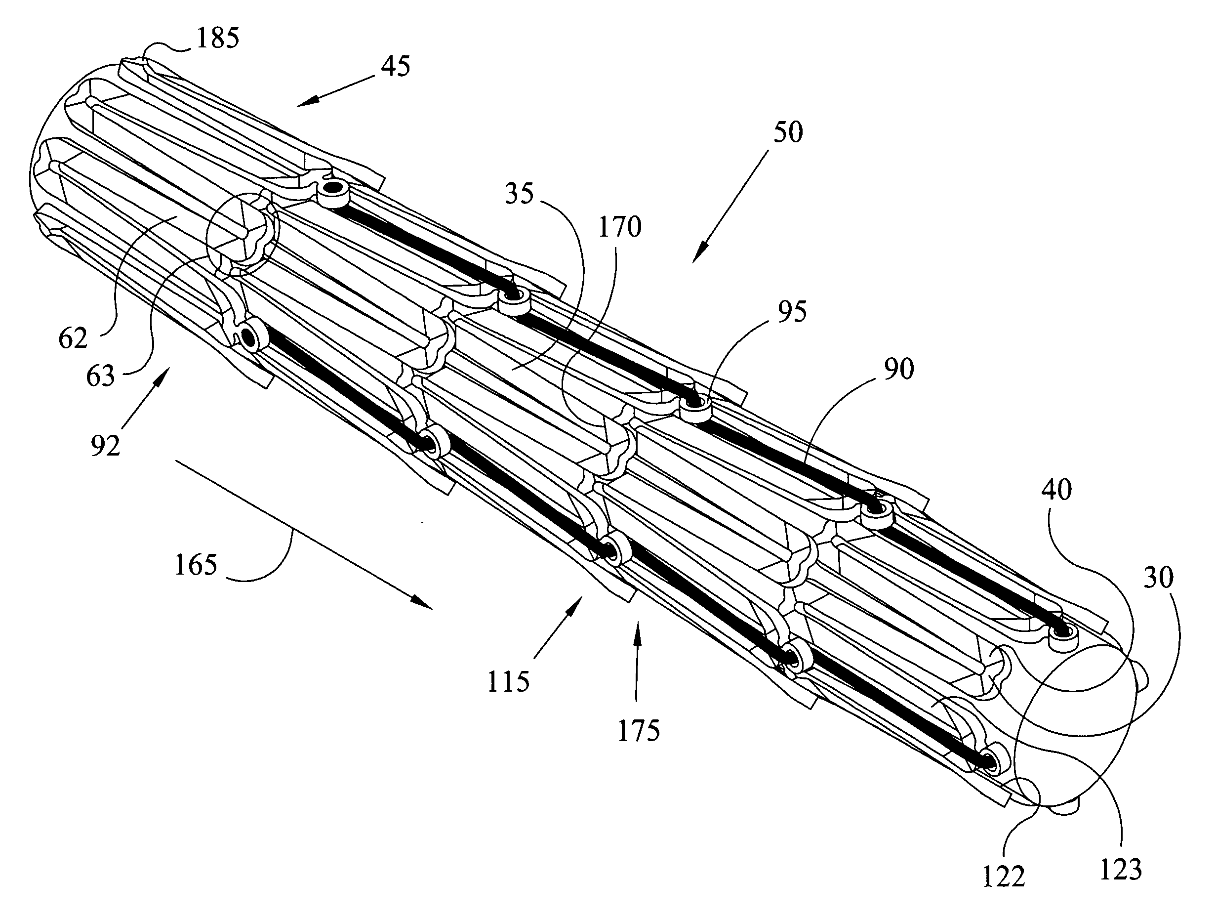
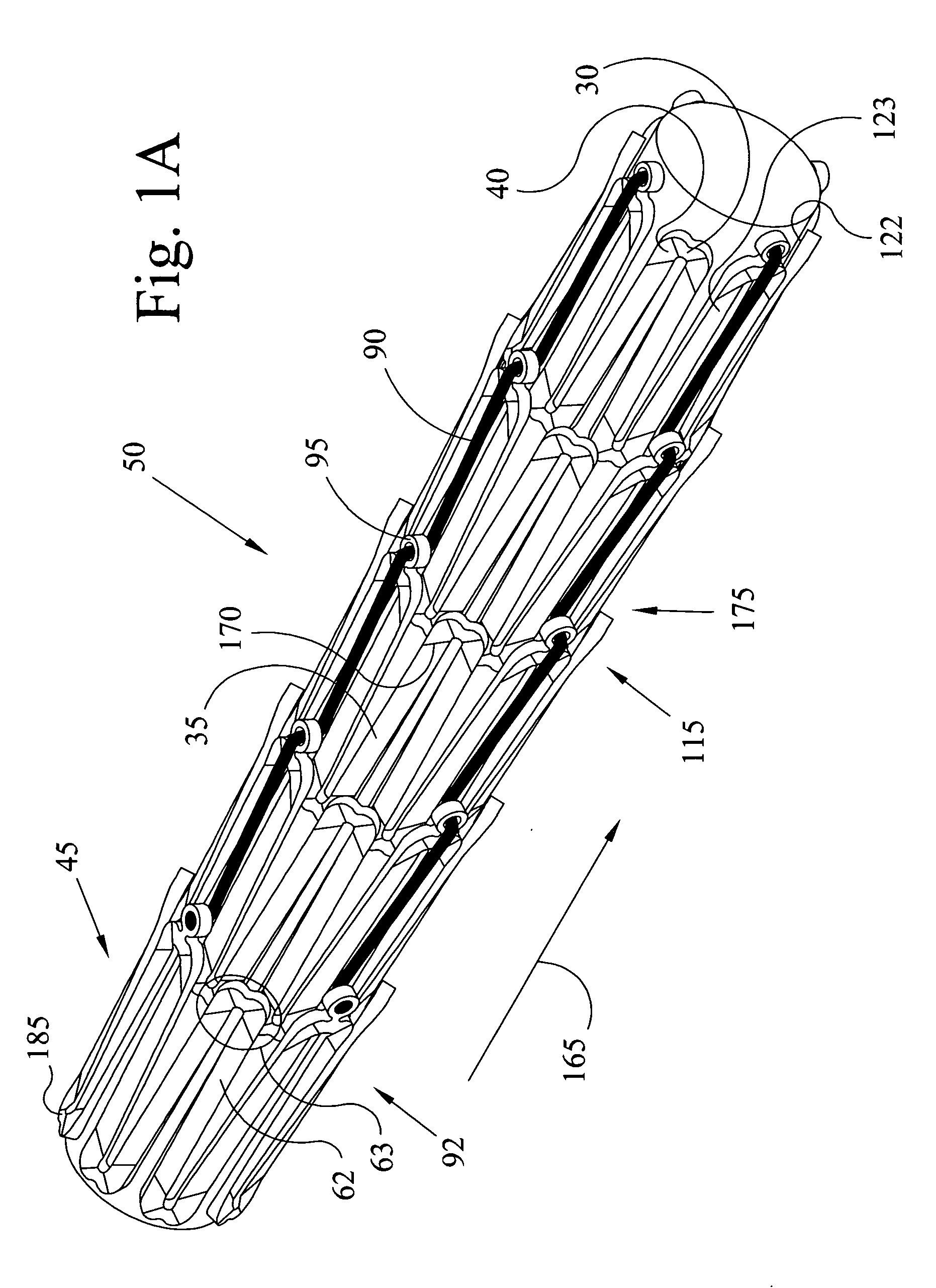
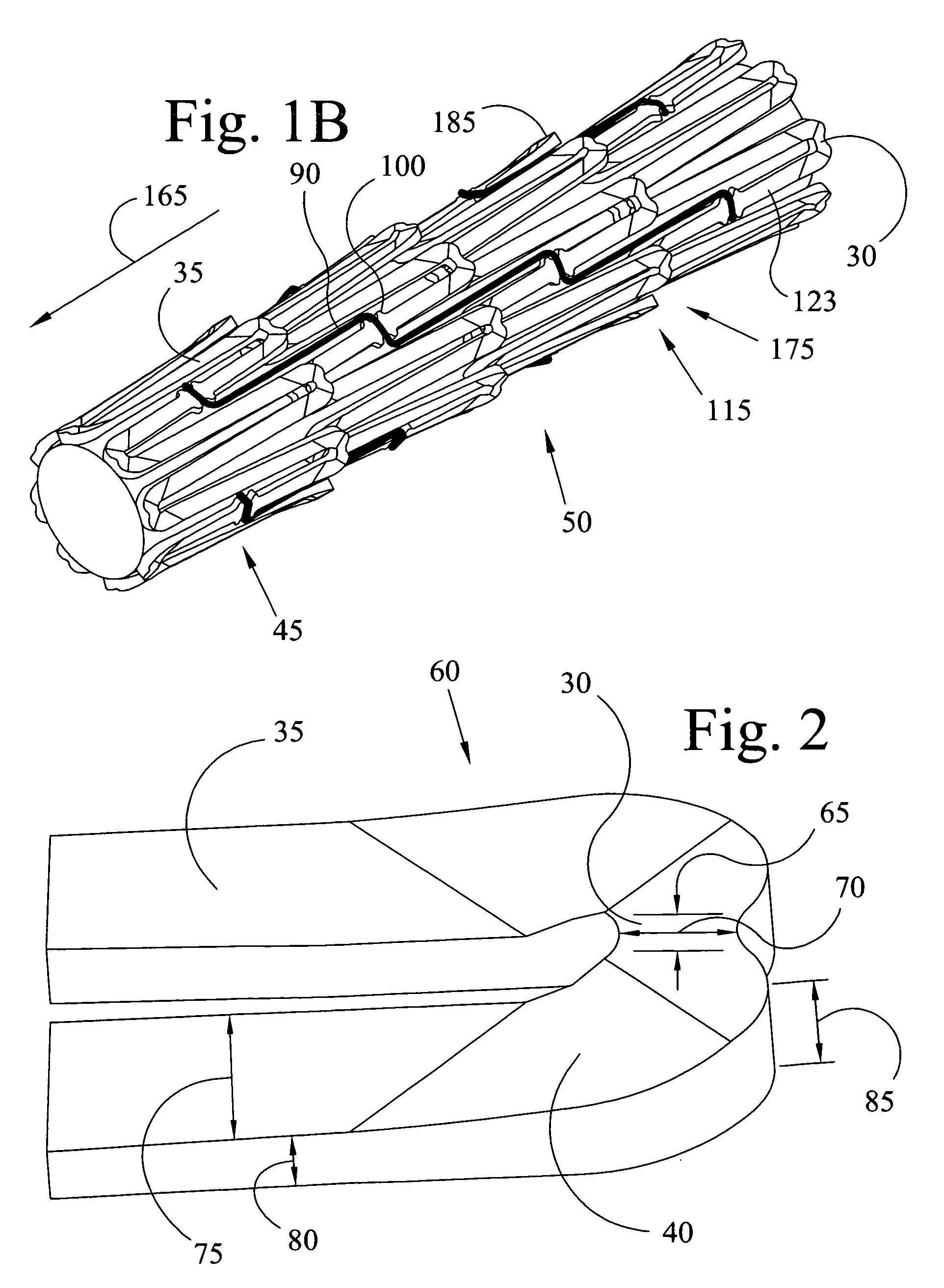
[0058]Embodiments of the present invention have a plurality of hinges (30) and struts (35) that are connected together via transition regions (40) as shown in FIGS. 1A, 1B, and 2. The embodiments of FIGS. 1A and 1B have joining elements (42) that are connecting fibers (90) to connect segments (45) of the stent (50). Alternate embodiments have joining elements (42) that are spacing members (55) to connect segments (45) as shown in FIGS. 3A and 3B. The struts (35) form the elongated elements (62) of the stent wall structure (60) and the hinges (30) and transition regions (40) form the junctional regions (63) of the wall structure (60) where one elongated element (62) joins with another elongated element (62). During deployment the hinge undergoes plastic deformation due to a small hinge length (65) and hinge width (70) (see FIG. 2) that focuses the expansion deformation as the stent (50) is exposed to a balloon dilation or other mechanical dilation. The strut (35) has a very large str...


PUM


Abstract

A peripheral stent with individual segments reduces the occurrence of fatigue fracture failure seen in vessels and tubes having bending and twisting movement. Segments can be attached via connecting fibers that biodegrade and offer the segments freedom of movement. The segments are balloon-expandable but will not be crushed by external forces placed upon the stent. Hinges and struts provide the stent with a plastic deformation during expansion and remain elastic if exposed to an oval shape. The segments overlap each other to provide improved scaffolding of the vessel wall and a greater flexibility during delivery. A composite stent having both balloon-expandable and self-expanding character has application in the venous system.

Description

CROSS REFERENCE TO RELATED APPLICATIONS[0001]This invention makes reference and thereby includes aspects of issued U.S. Pat. Nos. 6,421,763; 6,312,460; 6,475,237; 6,451,051 which describes stents and attachment means having hinges and struts. This patent application also makes reference to two provisional applications filed 15 Feb. 2008 by Joseph M. Thielen: Overlap Stent with application number 61065913 and Segmented Stent with application number 61066039.BACKGROUND OF THE INVENTION[0002]1. Field of Invention[0003]This invention pertains to stents delivered via an interventional catheter into tubular vessels of the body such as arteries or veins in a small diameter conformation and expanded to a larger diameter to hold the vessel outward and allow passage of fluid such as blood.[0004]2. Description of Prior Art[0005]Stents used in specific vessels of the body such as the superficial femoral artery (SFA), carotid artery (CA), iliac artery, popliteal artery, other arteries of the low...

Claims


Application Information

Patent Timeline
IPC IPC(8): A61F2/06
CPCA61F2/91A61F2230/0054A61F2002/91575A61F2/915A61F2/852
Inventor THIELEN, JOSEPH MICHAELDRASLER, WILLIAM JOSEPH
Owner FEMORALIS
Why Eureka
Try Eureka