Active mixer circuit and a receiver circuit or a millimeter-wave communication unit using it

a technology of active mixer and receiver circuit, which is applied in the field of active mixer circuit and receiver circuit or millimeter-wave communication unit using it, can solve the problems of reducing the s/n ratio and high supply voltage, and achieves low noise, high frequency, and low power consumption.

Active Publication Date: 2009-09-03
HITACHI LTD
View PDF5 Cites 38 Cited by
  • Summary
  • Abstract
  • Description
  • Claims
  • Application Information

AI Technical Summary

Benefits of technology

[0006]A mixer circuit, which is a circuit block that performs frequency conversion from a predetermined high frequency for wireless communication to a low frequency for demodulating a modulation signal modulated into a radio frequency signal in a receiver chain of a wireless communication system, needs to perform the frequency conversion with noise as low as possible and conversion gain as large as possible. Herein, the conversion gain is a ratio of signal amplitude of a radio frequency input to the mixer circuit to signal amplitude of an output frequency output from the mixer circuit. The higher the conversion gain is, the more the output signal amplitude with respect to the same input signal amplitude increases. The mixer circuit, which attenuates the signal amplitude having the conversion gain smaller than 1, is referred to as a passive mixer circuit, while the mixer circuit, which amplifies the signal amplitude having the conversion gain larger than 1, is referred to as an active mixer circuit. If properly designed, the active mixer circuit can improve signal-to-noise ratio (S / N ratio) to decrease deterioration of noise as compared to the passive mixer circuit, thus improving reception sensitivity of the receiver. As a result, the active mixer circuit is mainly used for wireless communication devices. Further, in the mixer circuit, there is a need to reduce the frequency signal that is included in the output signal but is not required for demodulation.
[0009]Further, when the double balanced mixer circuit suppresses and outputs the input local oscillator frequency signal, this is advantageous in that signal components that are included in the output signal are reduced but not required for demodulation, while the input single-ended signal into the differential signal needed to be previously converted. In the case of the receiver for wireless communication, since the input signal is a weak single-ended signal such that it can be received through an antenna, the insertion of the single-to-differential converter causes the decrease of the S / N ratio because of the decrease of the amplitude and the increase of the noise.
[0012]However, although the circuit configuration shown in FIG. 18 can improve the S / N ratio, the low-noise amplifier 121, which performs the voltage amplification, is connected to a pre-stage of the balun 122. In order to increase the gain, the supply voltage required for the low-noise amplifier approximately corresponds to the voltage required for the transistor having two-stages. Further, unlike the Gilbert cell type mixer circuit in the conventional art, the circuit configuration shown in FIG. 18 requires current for operating the low-noise amplifier 121 and current for operating the switch circuit (a multiplier) 123, respectively, which results in the increase of power consumption, including power consumed in the low-noise amplifier and the multiplier.
[0014]Therefore, it is an object of the present invention to provide a mixer circuit that is configured of semiconductor integrated circuits that are operated at low voltage, low noise, and low power consumption.
[0017]Effects obtained by a representative one of the inventions disclosed in the present specification will be briefly described below. In other words, the semiconductor integrated circuits including the active mixer circuit that requires a low supply voltage for operation can be provided. Further, the semiconductor integrated circuits including the active mixer circuit that is operated at high frequency, low noise, and low power consumption can be provided.

Problems solved by technology

A Gilbert cell type mixer circuit shown in FIG. 16, which is the mixer circuit in the conventional art, has a configuration that stacks transistors in three stages; however, there is a problem in that the supply voltage should be high in order to sufficiently secure an operating voltage of the transistor.
In the case of the receiver for wireless communication, since the input signal is a weak single-ended signal such that it can be received through an antenna, the insertion of the single-to-differential converter causes the decrease of the S / N ratio because of the decrease of the amplitude and the increase of the noise.

Method used


Image

  • Active mixer circuit and a receiver circuit or a millimeter-wave communication unit using it
  • Active mixer circuit and a receiver circuit or a millimeter-wave communication unit using it
  • Active mixer circuit and a receiver circuit or a millimeter-wave communication unit using it

Examples


first embodiment

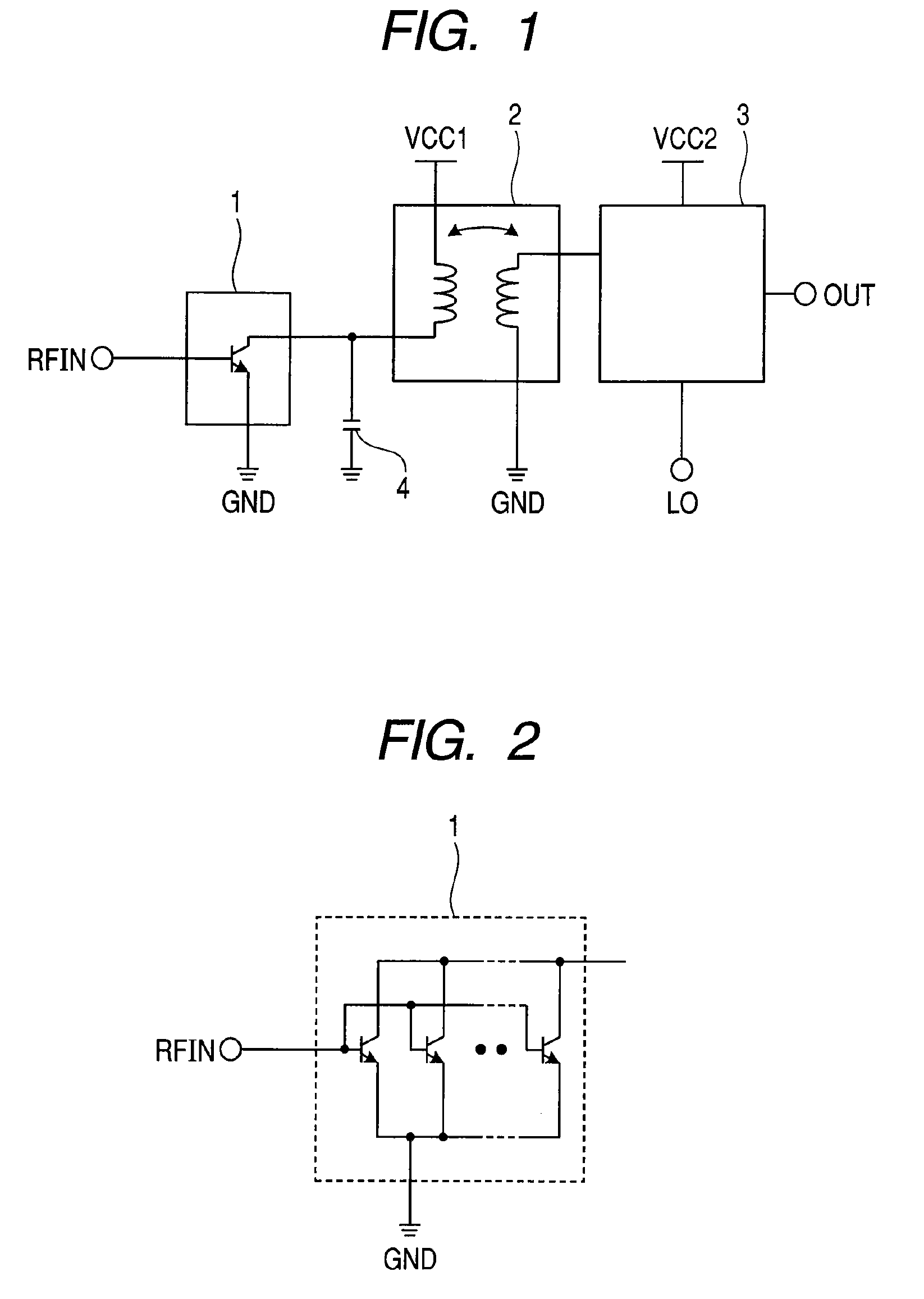
[0042]First, an active mixer circuit according to a first embodiment of the present invention will be described.

[0043]FIG. 1 is a diagram showing a block configuration of an active mixer circuit provided in a semiconductor integrated circuit according to one embodiment of the present invention. A transconductance amplifier 1 configuring a voltage-to-current converter receives a radio frequency signal RFIN from an input terminal RFIN, and converts voltage amplitude of the input signal into current amplitude and amplifies it. The converted input signal is input to one terminal (input terminal) of primary winding of a transformer 2. Further, supply voltage of the transconductance amplifier 1 is supplied from supply voltage VCC1 that is provided to the other terminal of the primary winding of the transformer 2, and direct bias current is supplied through the transformer 2 from the VCC1 and flows to a ground terminal of the transconductance amplifier 1.

[0044]One terminal of secondary win...

second embodiment

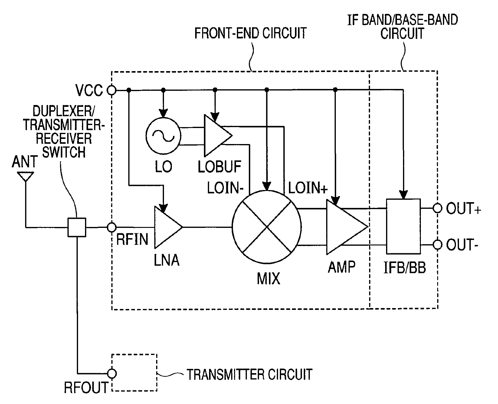
[0052]Hereinafter, a configuration example of a wireless communication receiver circuit as a semiconductor integrated circuit according to a second embodiment of the present invention will be described. FIG. 4 is a diagram showing a block configuration example of a wireless communication receiver circuit configured using the mixer circuit according to one embodiment of the present invention.

[0053]In FIG. 4, the wireless communication receiver circuit includes a low-noise amplifier LNA, a mixer circuit MIX, a local oscillator LO, a first differential amplifier LOBUF, and a second differential amplifier AMP. The low-noise amplifier LNA is supplied with an input signal RFIN of a first frequency that is received in an antenna of a receiver in a wireless system. An output node of the low-noise amplifier is connected to a first input node of the mixer circuit. A first output node of the local oscillator LO that oscillates and outputs a second frequency is connected to a first input node o...

third embodiment

[0056]Hereinafter, FIG. 5 is a view showing a block configuration of a mixer circuit provided in a semiconductor integrated circuit according to a third embodiment of the present invention. Unlike the embodiment of FIG. 1, the primary winding of a transformer 12 is a single-ended input and the secondary winding thereof is a differential output. One end of the primary winding is input with the single-ended signal and the other end thereof is connected to supply voltage VCC1. One end of the secondary winding of the transformer 12 outputs a differential positive phase signal, the other end thereof outputs a differential negative phase signals, and an intermediate node thereof is ground.

[0057]In other words, the transformer 12 includes the primary winding and the secondary winding having the intermediate node, wherein one end (first node) of the primary winding is connected to the input terminal of the single-ended signal of the transformer and the other end (second node) of the primary...


PUM


Abstract

The present invention provides a semiconductor integrated circuit including an active mixer circuit that is operated at low voltage, low noise, and low power consumption. It includes a transconductance amplifier, a transformer, and a multiplier, connects a transformer between the transconductance amplifier and the multiplier, and separates between the transconductance amplifier and the multiplier with respect to direct current inside the transformer. Further, each of the tranconductance amplifier and the multiplier is configured of transistors that are single-stacked between the supply voltage terminal and ground terminal.

Description

CLAIM OF PRIORITY[0001]The present application claims priority from Japanese Patent Application JP 2008-047723 filed on Feb. 28, 2008, the content of which is hereby incorporated by reference into this application.FIELD OF THE INVENTION[0002]The present invention relates to a mixer circuit that is mounted on a receiver for wireless communication or wired communication and performs frequency conversion, and more particularly, to a technology useful for providing an active mixer circuit having a low supply voltage and a receiver circuit or a millimeter-wave communication unit using it.BACKGROUND OF THE INVENTION[0003]As an example of a mixer circuit according to the conventional art, JP-A-2004-357091 discloses a Gilbert cell type double balanced mixer circuit shown in FIG. 16 (see FIG. 10 of JP-A-2004-357091). In the Gilbert cell type double balanced mixer circuit, one differential amplification transistor pair MB and MC is connected in series to a circuit where two differential switc...

Claims


Application Information

Patent Timeline
Patent Type & Authority Applications(United States)
IPC IPC(8): H04B1/16
CPCH03D7/1433H04B1/28H03D2200/0043H03D7/1458H03D2200/0023H03D7/1441
Inventor SHIRAMIZU, NOBUHIROMASUDA, TORUNAKAMURA, TAKAHIROWASHIO, KATSUYOSHITANABE, MASAMICHI
Owner HITACHI LTD
Why Eureka
Try Eureka