
Tissue engineering scaffolds

Inactive Publication Date: 2009-09-10
ORGAGEN INC
View PDF18 Cites 23 Cited by
  • Summary
  • Abstract
  • Description
  • Claims
  • Application Information

AI Technical Summary

Benefits of technology

[0029]In another embodiment, a tissue engineering scaffold of the present invention has at least one of the following: (i) a pore gradient where the pore diameter gradually decreases from about 100 microns at the exterior surface of the second tubular element to about 5 to about 15 microns at the interior surface of the first tubular element; (ii) a circumferential tube toughness of about 0.45 MJ / m3 to about 1.0 MJ / m3; (iii) an axial tube toughness of about 0.1 MJ / m3 to about 0.5 MJ / m3; (iv) a tangent delta of about 0.05 to about 0.3; and (v) a storage modulus of about 400 MPa to about 0.12 MPa. In one embodiment, the pore gradient contributes to the enhancement of cell seeding capacity for a TE scaffold. In another embodiment, the axial toughness and / or circumferential toughness contribute to the rendering of a scaffold resistant to fracture or tearing. In one other embodiment, the viscoelasticity of a TE scaffold is characterized by the tangent delta and / or storage modulus values.

Problems solved by technology

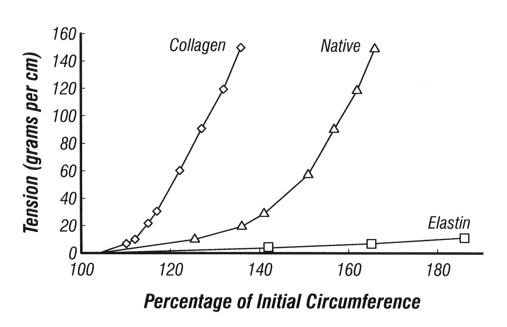
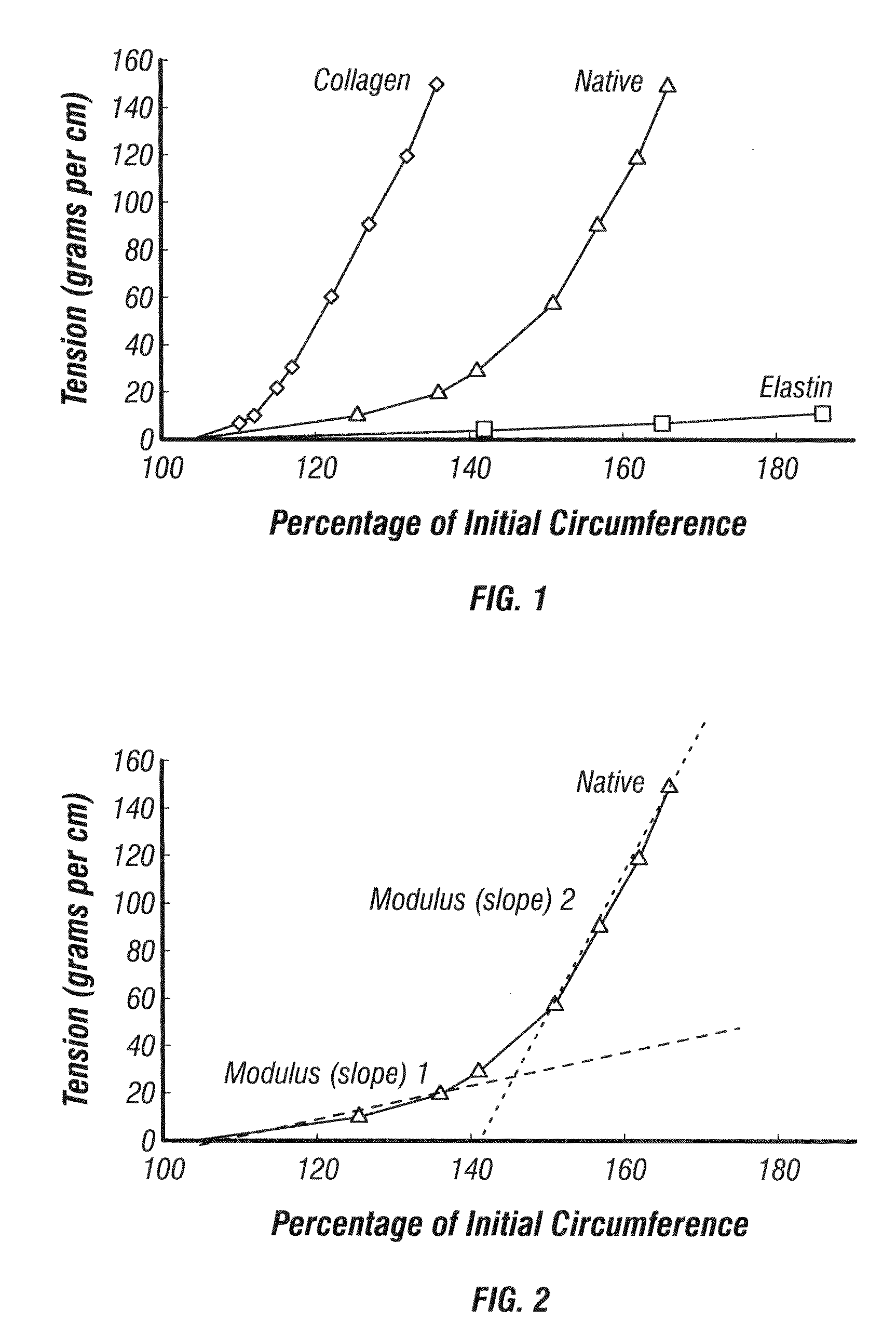
A major problem in blood vessel tissue engineering is the construction of vessel grafts that possess suitable, long-lasting biomechanical properties commensurate with native vessels.
Arterial replacements pose special challenges due to both the cyclic loading common to all vessels, but additionally the higher operating pressure required of those vessels.
However, although synthetic materials such as Dacron® (ethylene terephthalate) and PTFE (Teflon) have been successfully used for large diameter vessels, no synthetic material has been successfully utilized for small diameter (e.g. less than 6 mm internal diameter) vascular grafts.
Vascular grafts composed of Dacron® (ethylene terephthalate) and PTFE having an internal diameter of less than 5 mm have been found to be clinically unacceptable due to acute thrombus formation and chronic anastoinotic and / or intimal hyperplasia (Walpoth et al.
The elusive success of small-diameter vascular grafts might be in part attributable to factors including the failure to properly match in vivo mechanical properties.

Method used


Image

  • Tissue engineering scaffolds
  • Tissue engineering scaffolds
  • Tissue engineering scaffolds

Examples


example 1

Suture Wrap Over Latex Tubing

[0177]Generation of a “J”-shaped mechanical response in a two-component tubular architecture.

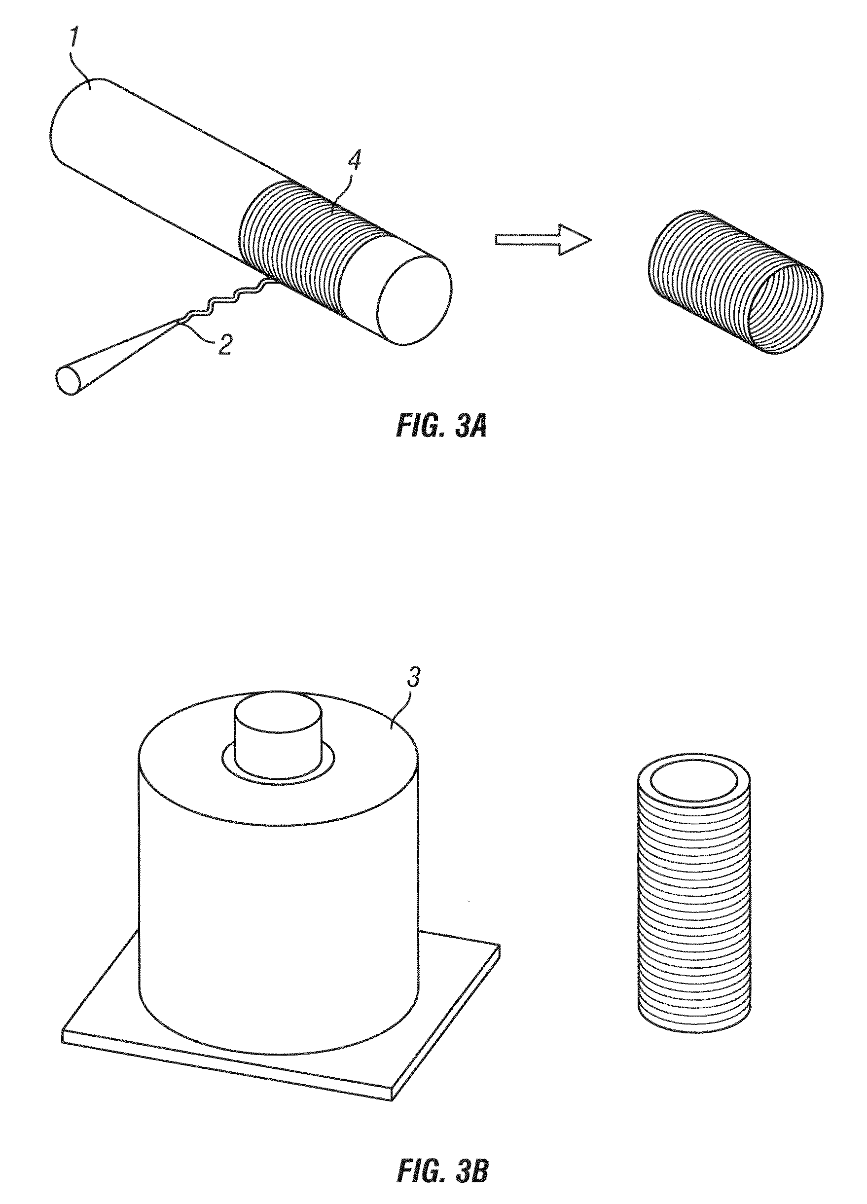
[0178]There are several ways in which the generation of a “J”-shaped mechanical behavior in a two-component system is possible. The results from the combination of an elastic inner layer coupled to a stiff outer layer (tensile element) are presented below. In this case, the inner layer is latex and the outer layer is suture, either wrapped polydioxannone (PDO), or stitched VICRYL™ (90:10 PLGA). FIG. 14A-B shows a scaffold made from VICRYL™ sutured around the outer circumference of a latex tube. Suture was applied while the latex tube was expanded to a larger diameter. The latex tube was photographed at its resting diameter which is why the suture, applied at a larger diameter is forming loops around the circumference of the latex tube. Scale bar is 0.5 cm. A) axial view B) lateral view.

[0179]Methods

[0180]Thin-walled latex tubing (Primeline Industries) with an inn...

example 2

[0188]A combination of an elastic inner layer coupled to a stiff outer layer (tensile element) was also examined. The inner layer is electrospun polyurethane (PU) and the outer layer is electrospun Poly glycolic acid (PGA).

[0189]Methods

[0190]10% PU in 1,1,1,3,3,3-Hexafluoro-2-propanol (HFIP) and 10% PGA in HFIP were the base solutions used in electrospinning. Approximately 2 milliliters of 10% PU was electrospun onto a 5 mm OD mandrel utilizing standard electrospinning procedures. Following completion, the PU tube was rolled off of the 5 mm OD mandrel and rolled onto an 8 mm OD mandrel. Use of a 5 mm OD and 8 mm OD mandrel equates to a 60% increase in circumferential length.

[0191]10% PGA was then electrospun onto the surface of the dilated PU tube until fully coated which equated to an overall volume of approximately 1 ml of the PGA solution. Following coating, the hybrid tube was removed while care was taken to minimize delamination.

[0192]Subsamples were taken from pure PU and PGA ...

example 3

Scaffold Formation Using an Expanding Mandrel

[0197]Here, we describe a novel method that successfully recapitulates the complex stress / strain behavior of native vessels through a multi-component architectural modification. In addition, the method presents opportunities for the “tuning” of these complex biomechanical properties through a combination of material selection and variations in the formation processes. Tubular scaffolds made with Tecothane 1074 or Poly(L-lactide-co-ε-caprolactone, and Polyglycolic acid knitted mesh tubing generated native vessel characteristic stress / strain behavior with moduli of 0.5 MPa-3.97 MPa and burst pressures averaging 1676 mm-Hg.

[0198]10% Polyurethane (PU: Tecothane 1074, Lubrizol, Inc.) and 12% Poly(L-lactide-co-ε-caprolactone) (PLCL: Lakeshore Biomaterials) were maintained as stock solutions in 1,1,1,3,3,3-Hexafluoro-2-propanol (HFIP: Sigma). 12 cm length tubes of these materials (4 mm-6 mm internal diameter, ˜4-5 ml of stock solution) were form...


PUM

PropertyMeasurementUnit
Lengthaaaaaaaaaa
Lengthaaaaaaaaaa
Pressureaaaaaaaaaa

Abstract

The present invention relates to tissue engineering scaffolds (TE scaffolds) that mimic the biomechanical behavior of native blood vessels, tissue engineered blood vessels (TEBVs) derived from the TE scaffolds, and methods of making and using the TE scaffolds and TEBVs.

Description

CROSS-REFERENCE TO RELATED APPLICATIONS[0001]This application claims priority under Section § 119(e) of the benefit of U.S. Provisional Application Ser. No. 61 / 028,860 filed Feb. 14, 2008, the disclosure of which is incorporated herein by reference in its entirety.FIELD OF THE INVENTION[0002]The present invention relates to tissue engineering scaffolds that mimic the biomechanical behavior of native blood vessels, and methods of making and using the same.BACKGROUND OF THE INVENTION[0003]A major problem in blood vessel tissue engineering is the construction of vessel grafts that possess suitable, long-lasting biomechanical properties commensurate with native vessels. Arterial replacements pose special challenges due to both the cyclic loading common to all vessels, but additionally the higher operating pressure required of those vessels. Researchers have approached this problem through a variety of synthetic and organic materials, different construction modalities (e.g. electrospinni...

Claims


Application Information

Patent Timeline
IPC IPC(8): C12N5/06B32B1/06B29C65/00A61F2/06
CPCA61F2/06B29C67/20Y10T156/1002D01D7/00D01D5/0076A61L27/14B32B37/02D01D5/00
Inventor RAPOPORT, H. SCOTTFISH, JEFFREY E.
Owner ORGAGEN INC
Learn More