Medical catheter tube and process for producing the same

a catheter tube and catheter tube technology, applied in the field of medical catheter tubes, can solve the problems of lowering productivity, not not aiming at raising the degree of freedom in controlling rigidity/flexible inclination, etc., to achieve superior positioning efficiency allowing movement, high degree of freedom, and high degree of freedom

Inactive Publication Date: 2009-09-24
KANEKA CORP
View PDF1 Cites 74 Cited by
  • Summary
  • Abstract
  • Description
  • Claims
  • Application Information

AI Technical Summary

Benefits of technology

[0037]By the means to solve problems according to the present invention (1) described above, the present invention provides a medical catheter tube superior in positioning efficiency allowing movement in accordance with guide wire and torque-transmitting efficiency when a surgeon applied a rotational force that has flexibility changing in the direction from the proximal region to the distal region. The configuration is also effective in providing a medical catheter tube giving a high degree of freedom in adjusting the rigidity / flexible balance and allowing adjustment of the rigidity / flexible balance according to access route, that shows kink resistance causing no crimping when bent in a complicated way and is superior in pressure resistance, guide wire compatibility, productivity, and others. The present invention gives a catheter tube showing favorable X-ray visibility, by forming a marker thereon by winding an X-ray-radiopaque metal part around the internal layer tube in the distal region, and, when the marker is flexible enough to bending deformation, the catheter becomes highly flexible in the particularly important distal and most distal regions. Thus, the present invention gives a medical catheter tube highly flexible in the distal region.
[0038]According to the present invention (2), when the resin tube is lubricating and flexible, the wire provides the catheter tube with kink resistance, pressure resistance, torque-transmitting efficiency, insertion efficiency, and others, and the external layer tube is flexible, it is possible to move the catheter tube smoothly forward and backward when a guide wire is inserted into the resin tubes of the catheter tube, and thus, to send the catheter tube together with both the wire and the external layer tube to a desirable treatment area.
[0039]According to the present invention (3), because the marker is an X-ray-radiopaque metal wire coil wound around the internal layer tube, a square X-ray-radiopaque metal sheet having slits cut from both sides wound around the internal layer tube, or a tube of a resin kneaded with a X-ray-radiopaque metal powder, it is possible to obtain a soft catheter tube that does not become hardened in the distal region.
[0040]According to the present invention (4), because the wire has a thermoplastic liquid crystal polymer as its internal core and a flexible polymer as its sheath, the catheter tube is improved in reinforcement effects such as pressure resistance and kink resistance, and the marker of an X-ray-radiopaque metal part in the distal region becomes more visible during use under X-Ray irradiation.
[0041]According to the present invention (5), advantageously because the pick distance of the braid forming the reinforcing material layer changes continuously or stepwise in the direction from the proximal region to the distal region, the rigidity of the catheter tube decreases gradually in the direction from the proximal region to the distal region.
[0042]According to the present invention (6), advantageously because the external layer tube has multiple segments and the multiple segments are aligned in such a manner that the Shore D hardness of the resins for the segments decreases stepwise in the direction from the proximal region to the distal region, the hardness of the catheter tube decreases gradually in the direction from the proximal region to the distal end and also the torque applied to the proximal region is transmitted more easily to the distal region.

Problems solved by technology

However, although it is possible to form a rigid proximal region and a flexible distal region on the catheter tube, the catheter tube is not aimed at raising the degree of freedom in controlling the rigidity / flexible inclination and adjusting the rigidity / flexible balance of catheter tube according to access route.
In addition, there was no specific description of a marker having X-ray visibility, and thus, it is not aimed at making the catheter distal region highly flexible and ensuring X-ray visibility simultaneously.
However, the degree of freedom in controlling the rigidity / flexible inclination is lower even in the configuration, and the elastic force of the ribbon-reinforcing material often lead to breakage of the internal tube-shaped liner or the external tube-shaped cover by the cutoff edge during production, lowering productivity.
In addition, there is no concept therein to adjust the rigidity / flexible balance of the catheter tube according to access route.
However, although it is possible to form a high-rigidity proximal region and a high-flexible distal region in the catheter tube and keep a favorable balance in flexural rigidity, the rigidity / flexible balance of the catheter tube is not intended to be adjustable according to access route.
Further in the catheter tube, the entire reinforcing coil is an X-ray-radiopaque metal wire; the flexible of the distal region is insufficient; and the X-ray visibility is excessively high, causing troubles in decision making by surgeons during operation.
However, although it is possible to form a rigid proximal region and a flexible distal region in the catheter tube, it is not aimed at raising the degree of freedom in controlling the rigidity / flexible inclination and adjusting the rigidity / flexible balance of catheter tube according to access route.
In addition, the X-ray visible marker is a marker formed by winding a metal sheet or a metal tube around the internal layer tube, and thus, it is not possible to ensure high flexibility of the catheter distal regions in the area close to and the periphery of the marker.
However, the step of removing part of the fabric intermittently in the machine direction by irradiation of a laser beam at a wavelength of 1.06 μm is very complicated.
The method is also lower in productivity, because, when a torque transmission region is formed continuously by applying a metal fabric continuously over the external surface of a thermoplastic tube having an inserted metal core wire and embedding the fabric into the outer surface of the tube by softening by heating to a depth of about ½ to ⅕ of the thickness in the downstream step, the metal fabric may cause problems such as ejection of the metal fabric out of the tube surface caused by the bending of cut edge due to its elastic force during embedment of the fabric by heat softening of the tube.
It is also difficult to control the inclination in rigidity and flexible sufficiently.
In addition, the rigidity / flexible balance of the catheter tube is not intended to be adjustable according to access route.
In addition, there is no specific description on the X-ray visible marker, and thus, it is not aimed at making the catheter distal region highly flexible and ensuring X-ray visibility simultaneously.

Method used


Image

  • Medical catheter tube and process for producing the same
  • Medical catheter tube and process for producing the same
  • Medical catheter tube and process for producing the same

Examples


Embodiment Construction

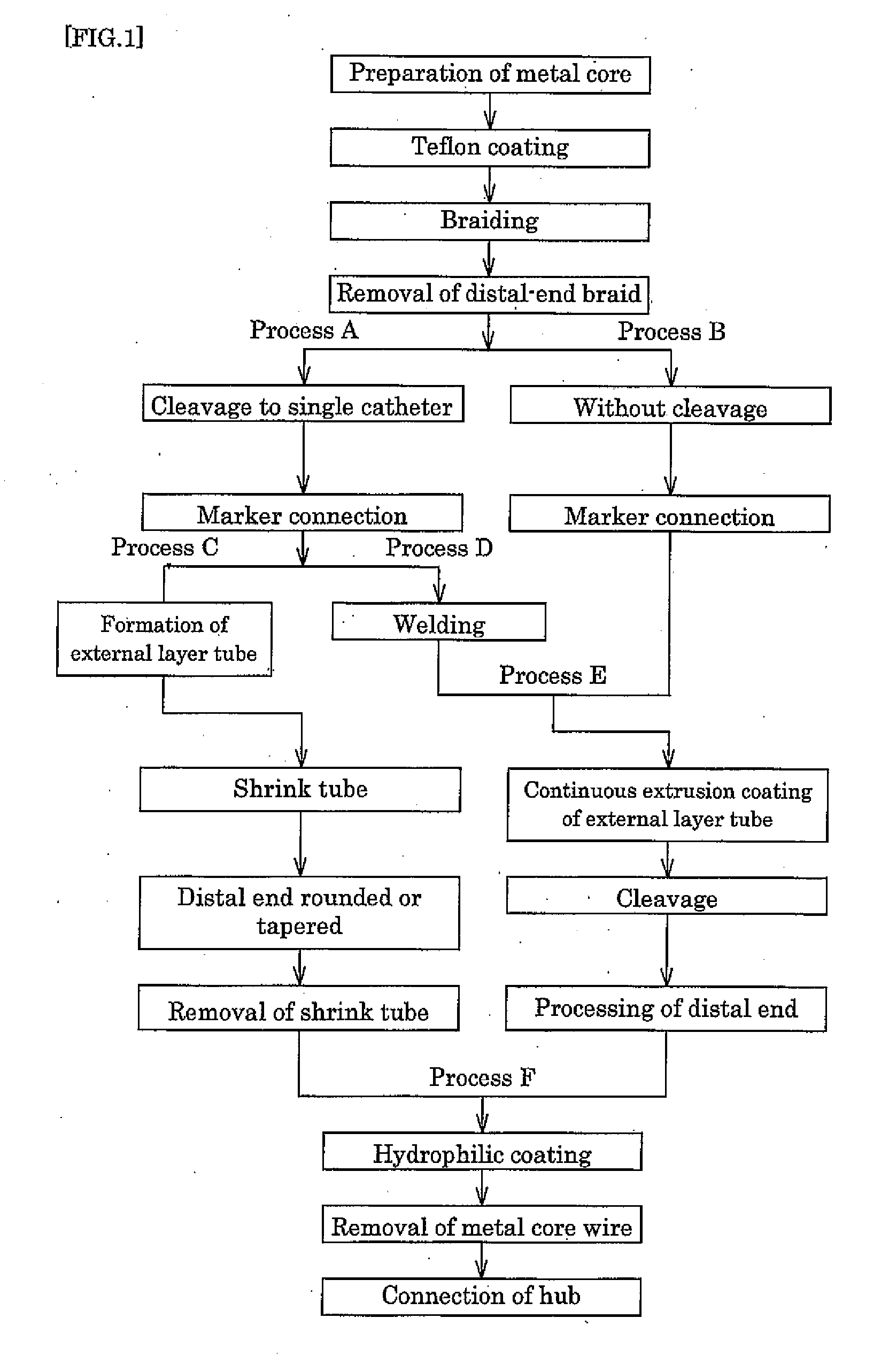
[0103]Hereinafter, the best mode of the medical catheter tube according to the present invention will be described with reference to drawings. These drawings are schematic drawings showing the characteristics of the configuration of the present invention, and the length and diameter of each region is arbitrary, if the catheter tube can be used favorably as a catheter tube for medical treatment. FIG. 1 is a flowchart showing the production process, and the best mode of the present invention will be described with reference to the Figure. In the present invention, various modifications are possible within the scope of the present invention specified by its claims.

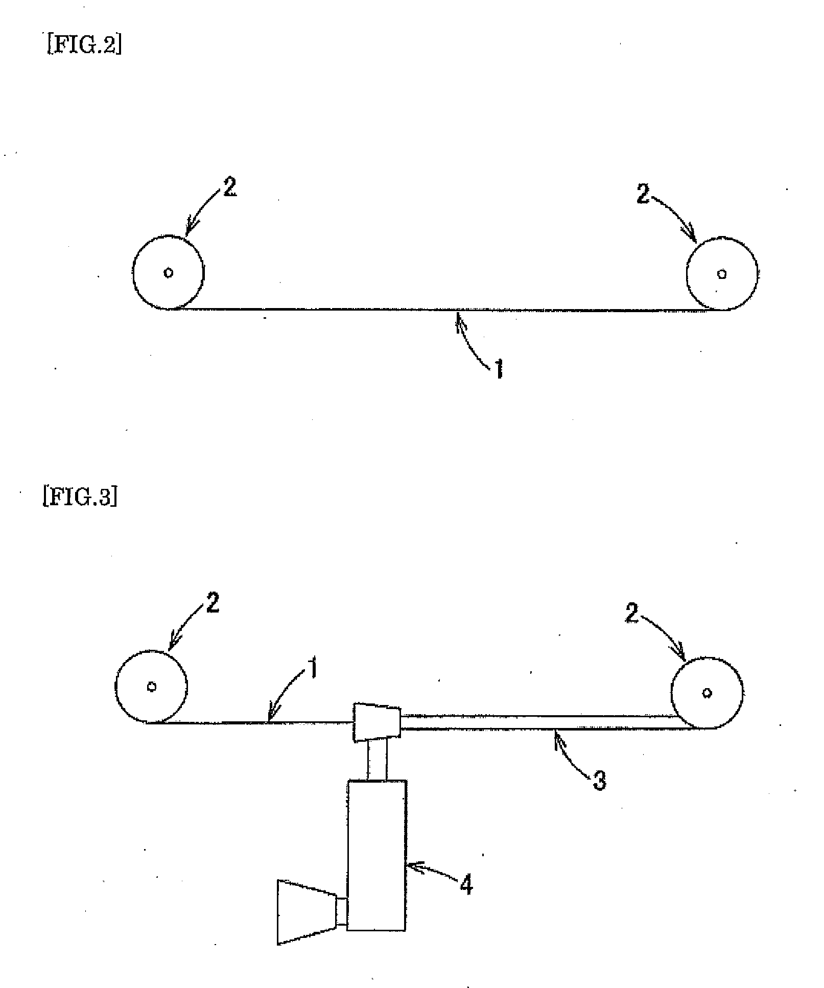
[0104]First, a metal core wire 1 is made available, as shown in FIG. 2. The metal core wire 1 is wound around reels 2; the external diameter of the wire corresponds roughly to the internal diameter of the catheter to be produced; and it is preferably a metal-plated conductor or a stainless steel wire. For convenience, in all ...


PUM

PropertyMeasurementUnit
constant widthaaaaaaaaaa
wavelengthaaaaaaaaaa
diameteraaaaaaaaaa

Abstract

There is provided a medical catheter tube capable of exhibiting excellent flexibility, and provided a process for producing the same. In particular, there is provided a medical catheter tube having, arranged from a base edge side, a base part, a forefront part and a cutting edge part The medical catheter tube comprises an inner layer tube of resin pipe; a reinforcing material layer produced by knitting of a wire around the inner layer tube; a marker disposed by winding and covering of the inner layer tube at the forefront part with a roentgenopaque metal member; and an outer layer tube of resin pipe covering the reinforcing material layer and the marker. The inner layer tube, reinforcing material layer, marker and outer layer tube of the medical catheter tube are united together.

Description

TECHNICAL FIELD[0001]The present invention relates to a medical catheter tube superior in flexibility, positioning efficiency, torque-transmitting efficiency, kink resistance, and pressure resistance, higher in the freedom of controlling the rigidity / flexible inclination, and allowing adjustment of rigidity / flexible balance according to various access routes, and a process for producing the same. The present invention relates to a medical catheter tube that shows favorable X-ray visibility in the distal region and also superior flexible at the same time, and a production method thereof.BACKGROUND ART[0002]Catheter tubes are hollow medical devices that are used as inserted in the cavity, vessel, blood vessel, and others in the body, specifically for selective injection of angiographic agent or others, removal of blood clot, recirculation of clogged vessel, vasodilation, and the like, and are normally tube-shaped. Such a catheter demands superior usability allowing rapid, accurate, an...

Claims


Application Information

Patent Timeline
Patent Type & Authority Applications(United States)
IPC IPC(8): A61M25/00B23P11/00B05D3/00
CPCA61M25/001Y10T29/49826A61M25/0053A61M25/0012
Inventor MURATA, TAKAHIRO
Owner KANEKA CORP
Why Eureka
Try Eureka