Method for manufacturing solid electrolytic capacitor

a solid electrolytic capacitor and manufacturing method technology, applied in the manufacture of electrolytic capacitors, superimposed coating processes, coatings, etc., can solve the problems of uneven distribution of the layer of conductive polymer forming the solid electrolytic layer, inability to obtain sufficient electrostatic capacitance, and difficulty in densely forming the above-mentioned solid electrolytic layer in the insides of fine pores of porous sintered bodies. , to achieve the effect of increasing the capacitance of the capacitor

Inactive Publication Date: 2009-10-01
SANYO ELECTRIC CO LTD +1
View PDF1 Cites 26 Cited by
  • Summary
  • Abstract
  • Description
  • Claims
  • Application Information

AI Technical Summary

Benefits of technology

[0011]The object of present invention is to provide a method for manufacturing a solid electrolytic capacitor with an increased capacitor capacitance and a decreased ESR.
[0009]Further, if constant current is continuously applied, the conductive polymer cathode layer formed by electrolytic polymerization is acceleratedly increased around the feeding point where the above-mentioned metal wire is brought into contact with the above-mentioned conductive polymer cathode layer formed by chemical polymerization. Consequently the distribution of the layer of the conductive polymer forming the solid electrolytic layer becomes uneven.

Problems solved by technology

The reason why the low ratio is that, since the anode body of the porous sintered body such as tantalum has nanoporous structure, it is difficult to densely form the above-mentioned solid electrolytic layer in the insides of fine pores of the porous sintered body.
Therefore, there is a problem that no sufficient electrostatic capacitance can be obtained.
Consequently the distribution of the layer of the conductive polymer forming the solid electrolytic layer becomes uneven.

Method used


Image

  • Method for manufacturing solid electrolytic capacitor
  • Method for manufacturing solid electrolytic capacitor
  • Method for manufacturing solid electrolytic capacitor

Examples


example 1

[0030]Hereinafter, Example 1 will be described.

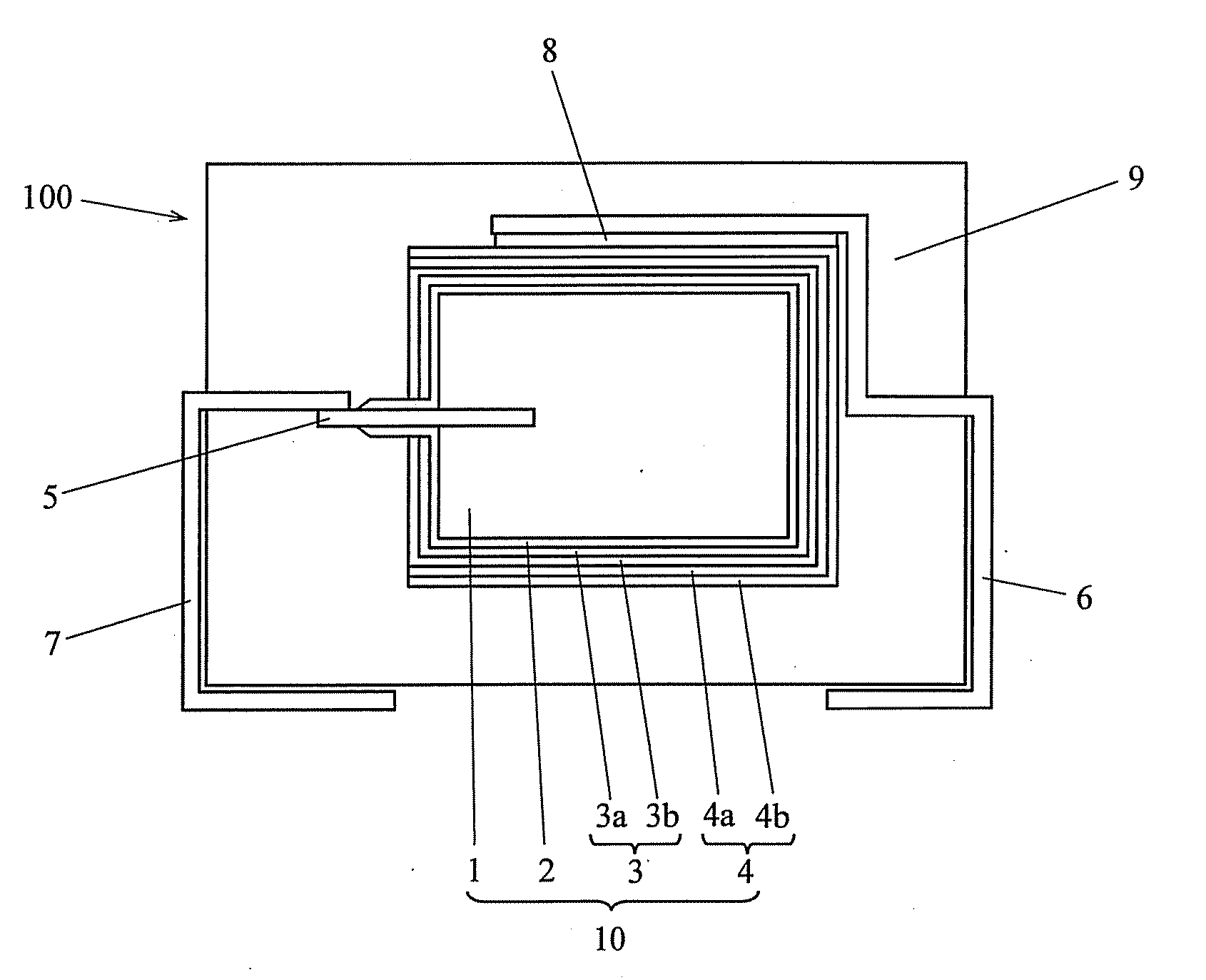
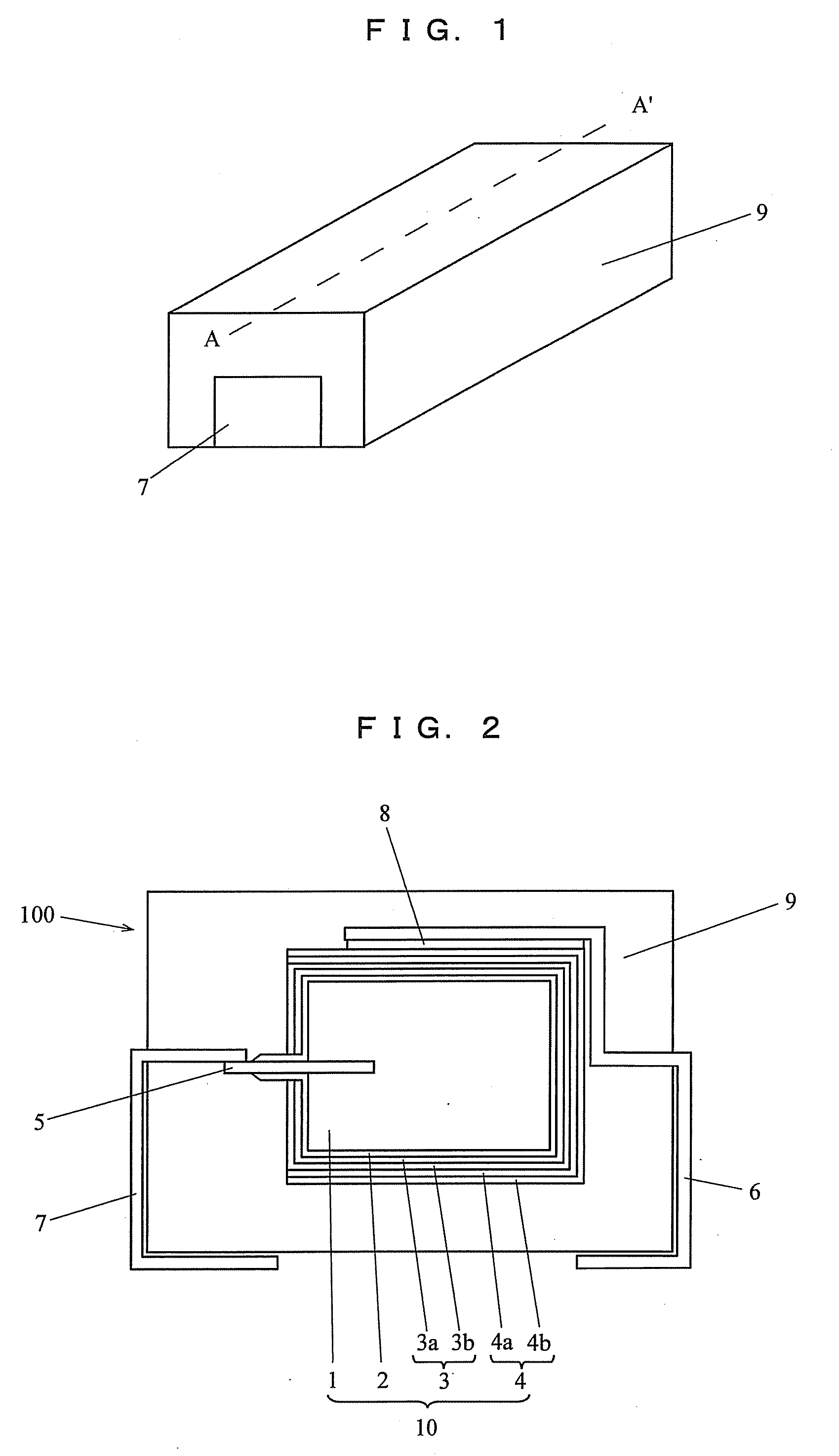
[0031]In a step of forming a dielectric coating layer 2, a porous anode body 1, which was obtained by sintering 100 mg of tantalum powder having CV product (a product of a capacity and a voltage) of 46000 μFV / g with an embedded tantalum wire to be an anode lead 5, was subjected to conversion treatment in aqueous solution containing 0.05% by mass of phosphoric acid at a voltage of 40 V to form the dielectric coating layer 2 on the surface of the anode body 1. The electrostatic capacitance in water (measured in an aqueous 8 N sulfuric acid solution) of the anode 1 subjected to the conversion treatment was 133 μF.

[0032]Next, in a chemical polymerization step, the anode body 1 subjected to the conversion treatment was immersed in an aqueous oxidizing agent solution prepared by dissolving 5% by mass of hydrogen peroxide and 1% by mass of sulfuric acid and taken out from the aqueous oxidizing agent solution and thereafter, exposed to pyrrole ...

example 2

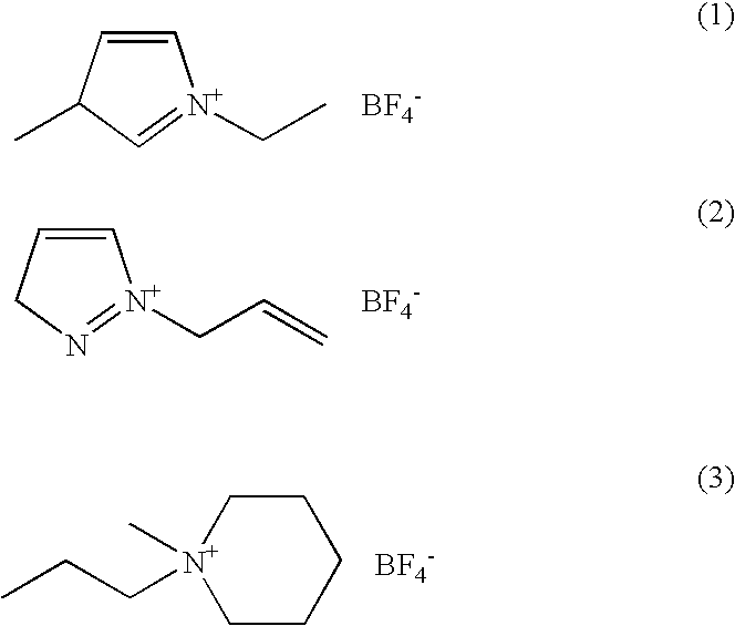
[0038]A capacitor element 10 was produced in the same manner as that of Example 1, except that an electrolytic polymerization solution containing 0.2 mol / L of pyrrole as a polymerizable monomer and 1-methyl-3-allylimidazolium tetrafluoroborate (MAI-BF4) as an ionic liquid was used, in the electrolytic polymerization step of forming the second solid electrolytic layer 3b of Example 1. A solid electrolytic capacitor was produced in the same manner as that of Example 1, except for using the above-obtained electrolytic capacitor element.

example 3

[0039]A capacitor element 10 was produced in the same manner as that of Example 1, except that an electrolytic polymerization solution containing 0.2 mol / L of pyrrole as a polymerizable monomer and N-methyl-N-propylpiperidinium bis (tetrafluoroborate) imide (MPPI -BF4) as an ionic liquid was used, in the electrolytic polymerization step of forming the second solid electrolytic layer 3b of Example 1. A solid electrolytic capacitor was produced in the same manner as that of Example 1, except for using the above-obtained electrolytic capacitor element.


PUM

PropertyMeasurementUnit
voltageaaaaaaaaaa
electrostatic capacitanceaaaaaaaaaa
capacitanceaaaaaaaaaa

Abstract

A method for manufacturing a solid electrolytic capacitor having a capacitor element produced by the steps of: forming a dielectric coating layer on the surface of an anode body, forming a conductive polymer cathode layer on the dielectric coating layer, and forming a cathode lead-out layer on the conductive polymer cathode layer, wherein the step of forming the conductive polymer cathode layer includes an electrolytic polymerization step of forming the conductive polymer cathode layer on the surface of the anode body on which the dielectric coating layer is formed by electrolytic polymerization using an electrolytic polymerization solution containing at least a monomer to be polymerized into the conductive polymer and an ionic liquid.

Description

BACKGROUND OF THE INVENTION[0001]1. Field of the Invention[0002]The present invention relates to a method for manufacturing a solid electrolytic capacitor, particularly a method for manufacturing a solid electrolytic capacitor with an increased capacitance and a decreased ESR (equivalent series resistance).[0003]2. Description of the Related Art[0004]In recent years, along with digitalization and increase of frequency of electronic appliances, solid electrolytic capacitors are also required to having higher capacities than those of conventional ones and be excellent in impedance property in a high frequency region. This solid electrolytic capacitor 100, as shown in FIG. 1 and FIG. 2, is completed by following steps. Specifically, first, a capacitor element 10 is produced by the steps : forming a dielectric coating layer 2 by oxidizing the surface of an anode body 1 having a structure in which an anode lead 5 is implanted in a sintered body made of a valve metal (tantalum, niobium, t...

Claims


Application Information

Patent Timeline
Patent Type & Authority Applications(United States)
IPC IPC(8): H01G9/025C25D5/10
CPCH01G9/025H01G9/0036
Inventor YOSHIMITSU, SATORU
Owner SANYO ELECTRIC CO LTD
Why Eureka
Try Eureka