Rolling bearing

a technology of rolling bearings and rolling bearings, applied in the direction of roller bearings, mechanical equipment, solid-state diffusion coatings, etc., can solve the problems of contaminated environment, insufficient improvement of components, easy breakage, etc., to reduce the hardness of components, improve durability, and improve dry-run performance

Inactive Publication Date: 2009-10-01
NTN CORP
View PDF26 Cites 16 Cited by
  • Summary
  • Abstract
  • Description
  • Claims
  • Application Information

AI Technical Summary

Benefits of technology

[0010]Accordingly, an object of the present invention is to provide a rolling bearing capable of attaining not only suppression of reduction in hardness of components in a high-temperature environment and improvement in durability in a contaminated environment but also improvement of dry-run performance.

Problems solved by technology

More specifically, a rolling bearing employed in a contaminated environment penetrated by hard foreign matter may be damaged in an early stage (in an operating time shorter than a calculated life of the bearing) due to gripping of the foreign matter.
On the other hand, a rolling bearing used in an insufficiently lubricated environment may cause seizure.
Even if the nitrogen-enriched layers are formed on the surface layer portions of the components such as the race member and the rolling elements made of the steel containing at least 3.75 mass % of chromium by the aforementioned plasma nitriding, however, the characteristics of the components may not be sufficiently improved.
Further, breakage may be easily caused when impactive stress is applied to the aforementioned components (reduction in toughness).
Thus, sufficient characteristics may not necessarily be attained particularly in fatigue strength and toughness when merely nitrogen-enriched layers are formed on the components such as the race member and the rolling elements made of the steel containing at least 3.75 mass % of chromium, although the surface layer portions thereof are improved in hardness.
The environment in which the rolling bearing is used is becoming increasingly severe.
Therefore, conventional countermeasures including those disclosed in the aforementioned Patent Documents 1 to 4 cannot necessarily be regarded as sufficient.

Method used


Image

  • Rolling bearing
  • Rolling bearing
  • Rolling bearing

Examples


first embodiment

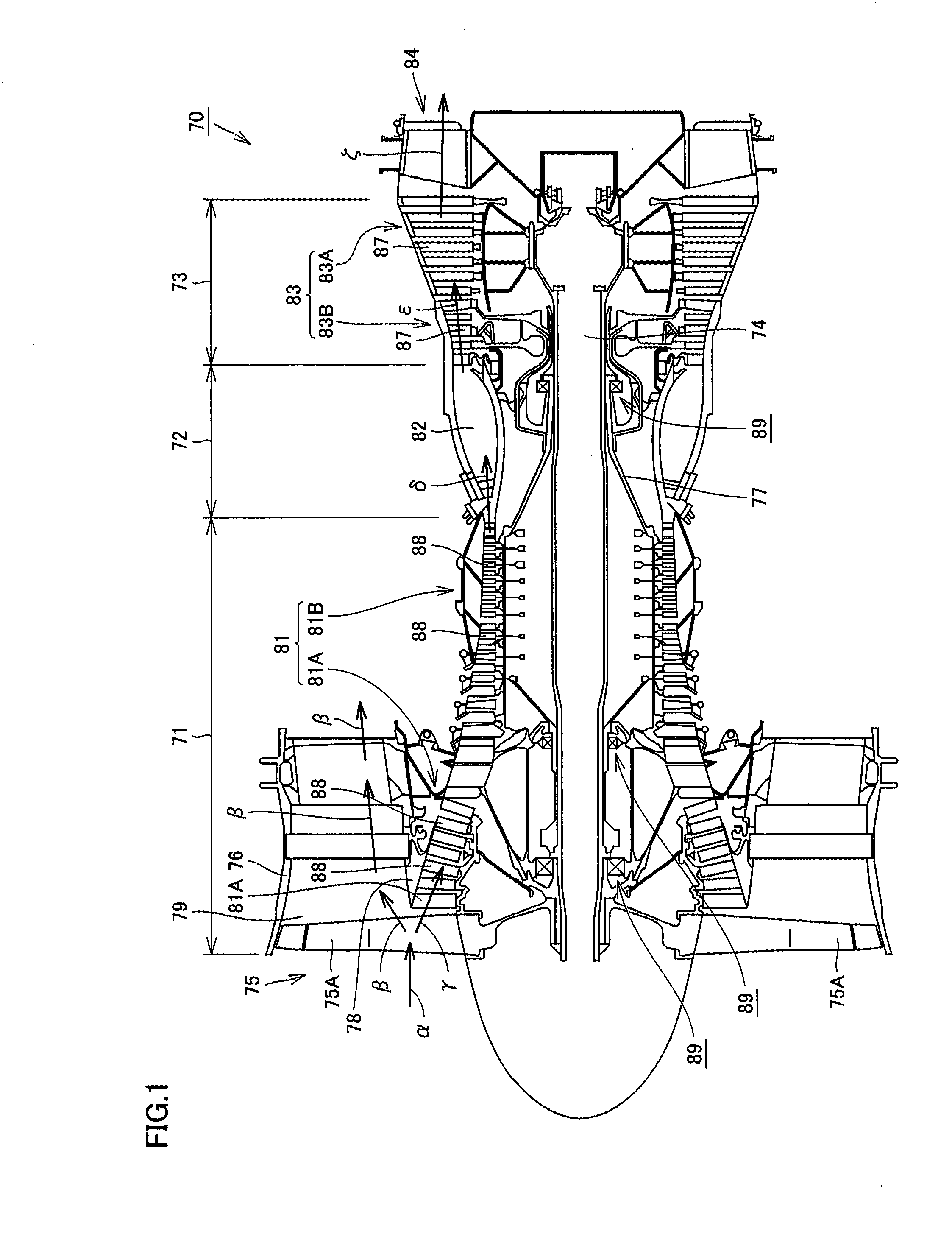
[0122]First, the structure of a turbofan engine according to a first embodiment of the present invention is described with reference to FIG. 1.

[0123]Referring to FIG. 1, a turbofan engine 70 includes a compression portion 71, a combustion portion 72 and a turbine portion 73. Turbofan engine 70 further includes a low-pressure main shaft 74 so arranged as to reach turbine portion 73 from compression portion 71 through combustion portion 72 and a high-pressure main shaft 77 so arranged as to enclose the outer peripheral surface of low-pressure main shaft 74.

[0124]Compression portion 71 includes a fan 75 having a plurality of fan blades 75A connected to low-pressure main shaft 74 and so formed as to radially outwardly protrude from low-pressure main shaft 74, a fan nacelle 76 enclosing the outer peripheral side of fan 75 and extending toward combustion portion 72 and a compressor 81 arranged on the side closer to combustion portion 72 as viewed from fan 75. Compressor 81 has a low-press...

second embodiment

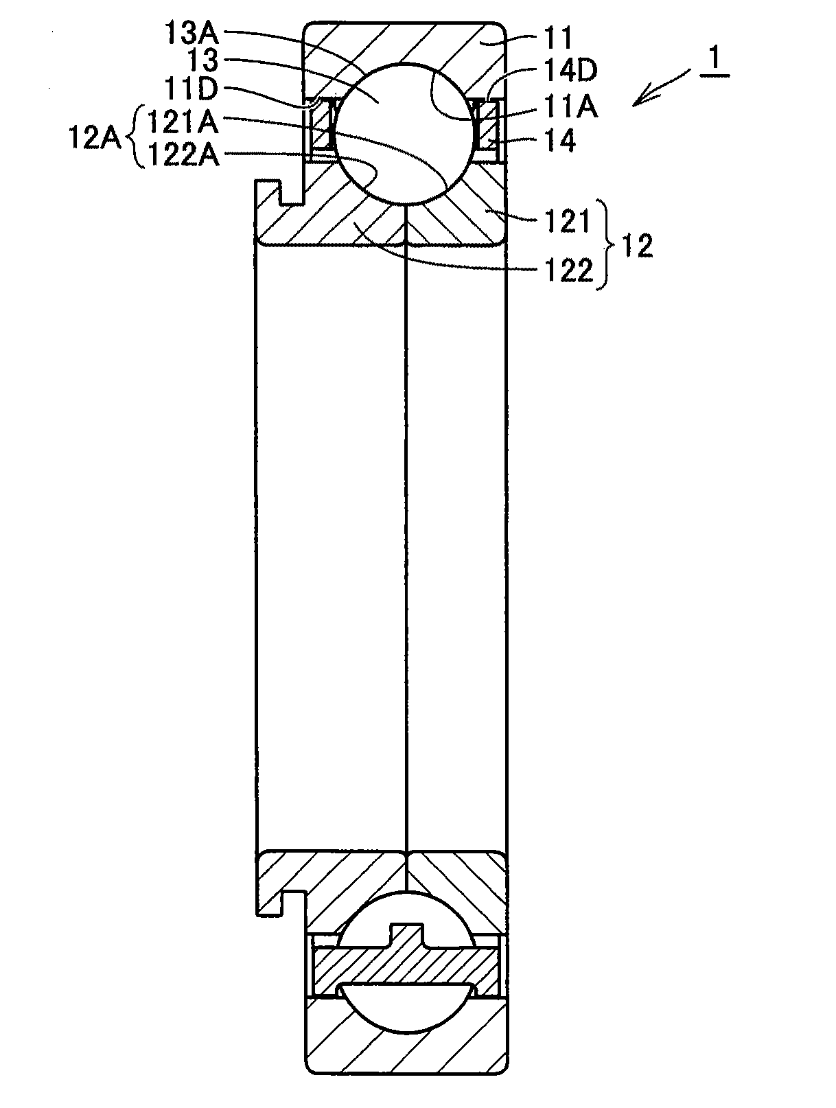
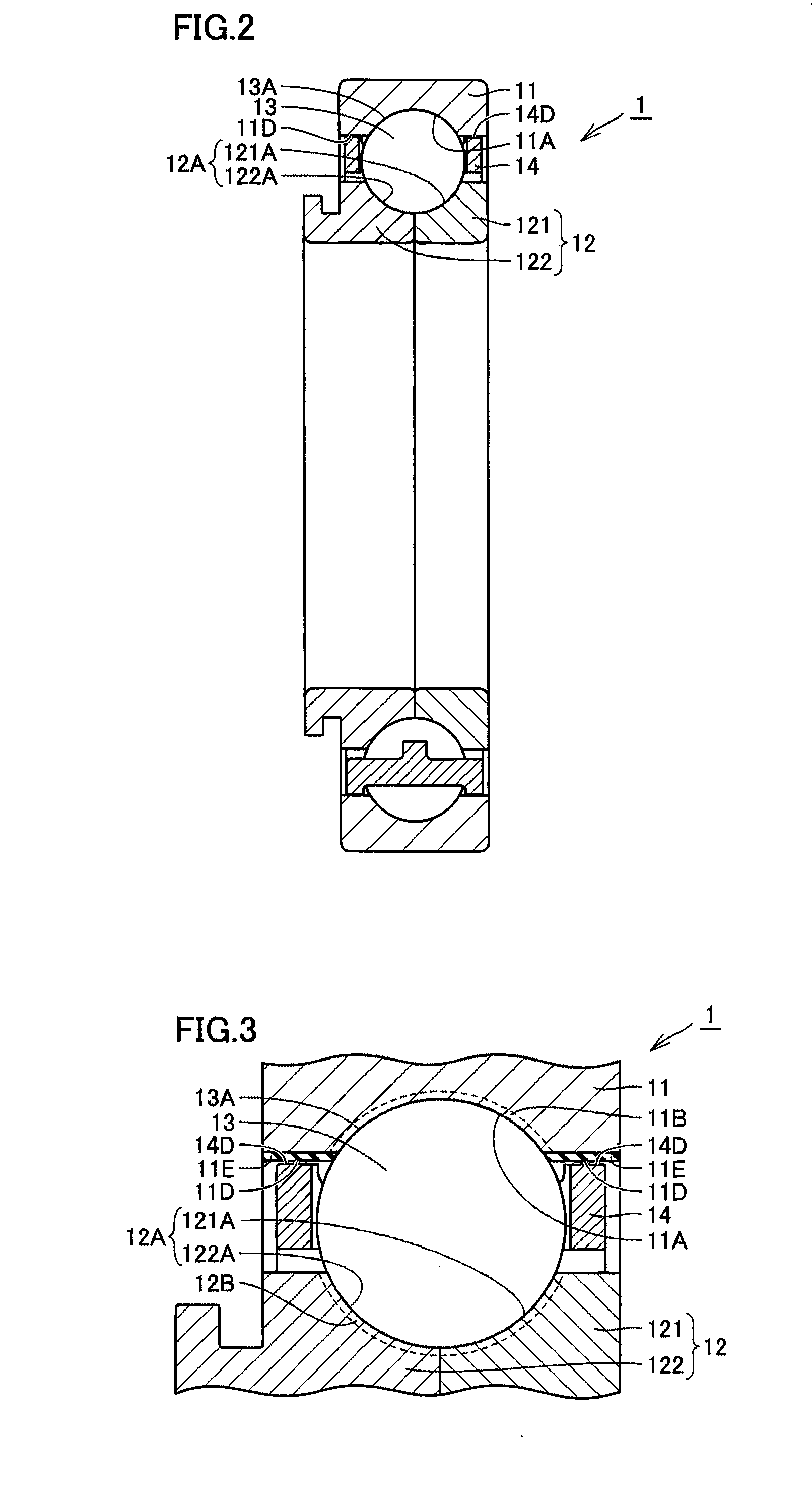
[0171]A second embodiment of the present invention is now described. Referring to FIGS. 6 and 7, a cylindrical roller bearing 2 according to the second embodiment is basically similar in structure to three-point contact ball bearing 1 according to the first embodiment, and exhibits functions / effects similar to those of three-point contact ball bearing 1. In other words, cylindrical roller bearing 2 includes an annular outer ring 21, an annular inner ring 22 arranged inside outer ring 21 and a plurality of rollers 23 as rolling elements arranged between outer ring 21 and inner ring 22 and retained in an annular cage 24. Rollers 23 are cylindrical. An outer ring rolling surface 21A is formed on the inner peripheral surface of outer ring 21, while an inner ring rolling surface 22A is formed on the outer peripheral surface of inner ring 22. Outer ring 21 and inner ring 22 are so arranged that inner ring rolling surface 22A and outer ring rolling surface 21A are opposed to each other. Pl...

third embodiment

[0178]A third embodiment of the present invention is now described. Referring to FIGS. 8 and 9, a cylindrical roller bearing 3 according to the third embodiment is basically similar in structure to three-point contact ball bearing 1 and cylindrical roller bearing 2 according to the first and second embodiments, and exhibits similar functions / effects. In other words, cylindrical roller bearing 3 includes an outer ring 31 corresponding to outer rings 11 and 21, an inner ring 32 corresponding to inner rings 12 and 22, rollers 33, corresponding to balls 13 and rollers 23, in contact with outer ring 31 and inner ring 32 on roller rolling surfaces 33A and a cage 34 corresponding to cages 14 and 24. Outer ring 31 and inner ring 32 include an outer ring nitrogen-enriched layer 31B corresponding to outer ring nitrogen-enriched layers 11B and 21B and an inner ring nitrogen-enriched layer 32B corresponding to inner ring nitrogen-enriched layers 12B and 22B on regions including an outer ring ro...


PUM

PropertyMeasurementUnit
thicknessaaaaaaaaaa
lengthaaaaaaaaaa
lengthaaaaaaaaaa

Abstract

An outer ring and an inner ring of a rolling bearing are constituted of steel containing 0.77 to 0.85% of carbon, 0.01 to 0.25% of silicon, 0.01 to 0.35% of manganese, 0.01 to 0.15% of nickel, 3.75 to 4.25% of chromium, 4 to 4.5% of molybdenum and 0.9 to 1.1% of vanadium with the rest consisting of iron and impurities, a nitrogen-enriched layer having a nitrogen concentration of at least 0.05 mass % is formed on a region including a rolling surface, and the total of a carbon concentration and the nitrogen concentration in the nitrogen-enriched layer is at least 0.82 mass % and not more than 1.9 mass %. A DLC coating layer is arranged on a region including an outer ring contact surface.

Description

BACKGROUND OF THE INVENTION[0001]1. Field of the Invention[0002]The present invention relates to a rolling bearing, and more specifically, it relates to a rolling bearing suppressing occurrence of seizure.[0003]2. Description of the Background Art[0004]Following the recent improvement in performance and efficiency of a mechanical device employing a rolling bearing, high durability in a severe environment tends to be required to the rolling bearing. More specifically, a rolling bearing employed in a contaminated environment penetrated by hard foreign matter may be damaged in an early stage (in an operating time shorter than a calculated life of the bearing) due to gripping of the foreign matter. On the other hand, a rolling bearing used in an insufficiently lubricated environment may cause seizure. Such seizure is easily caused particularly between a cage constituting the rolling bearing and a race member such as an inner ring or an outer ring guiding the cage. When the rolling beari...

Claims


Application Information

Patent Timeline
Patent Type & Authority Applications(United States)
IPC IPC(8): F16C33/62
CPCF16C33/3806F16C33/64F16C33/583F16C19/06F16C19/26F16C2360/23F16C2204/60
Inventor MORISHITA, HIROSHIITO, TAKASHIAKAI, CHIKAGEOHKI, CHIKARAYAGITA, KAZUHIRO
Owner NTN CORP
Why Eureka
Try Eureka