
Honeycomb structure and method for manufacturing the same

a technology of honeycomb and silicon carbide, which is applied in the direction of dispersed particle separation, transportation and packaging, and separation processes, etc., can solve the problems of high raw material yield, defect sometimes caused, and damage to the honeycomb structure formed by using silicon carbide as the framework, so as to reduce the pressure loss of fluid flowing into the cell, inhibit the damage of partial segments, and high thermal shock resistance

Inactive Publication Date: 2009-10-08
NGK INSULATORS LTD
View PDF8 Cites 7 Cited by
  • Summary
  • Abstract
  • Description
  • Claims
  • Application Information

AI Technical Summary

Benefits of technology

[0005]The present invention has been made in view of the above problems and aims to provide a honeycomb structure excellent in thermal shock resistance and a method for manufacturing a honeycomb structure, the method being capable of manufacturing the honeycomb structure efficiently in good raw material yield.
[0017]Since a honeycomb structure of the present invention is provided with a honeycomb structured portion having a plurality of partial segments separated and formed by a plurality of slits extending in a cell extension direction and not reaching at least one of the end faces and buffer portions formed by filling a filler in the slits, a partial segment can be made small even for a large honeycomb structure, thereby inhibiting the partial segments from being damaged due to a thermal shock. In addition, since spaces (slits) between partial segments are filled with a buffer portion, the honeycomb structure has high thermal shock resistance as a whole. Further, since there is a portion having no slit or buffer portion on at least one end face side of the honeycomb structure, pressure loss when a fluid is allowed to flow into the cells can be reduced.
[0018]According to a method for manufacturing a honeycomb structure of the present invention, since a honeycomb structure is formed by obtaining a honeycomb formed article by extrusion-forming, forming slits so as to separate and form partial segments, and forming buffer portions so as to fill the slits, a coarse machining step is unnecessary, and a raw material yield can be improved drastically.

Problems solved by technology

Since silicon carbide has relatively high thermal expansion coefficient, a honeycomb structure formed by using silicon carbide as the framework sometimes has a defect due to a thermal shock upon use when a large structure is formed.
In addition, a defect is sometimes caused by a thermal shock upon combusting and removing trapped particulate matter.
Therefore, there arise problems that an extra step such as an outer periphery coarse machining step is required and that the raw material yield is not high because the outer periphery is subjected to coarse machining.
In addition, even in a honeycomb structure formed by bonding honeycomb segments, internal heat generation upon combusting and removing particulate matter is large, and therefore a crack is prone to be caused inside the honeycomb structure.
Further, in a honeycomb structure formed by bonding honeycomb segments, pressure loss is prone to be large when a fluid is allowed to flow into the cells since the portion where the segments are bonded becomes thick.

Method used


Image

  • Honeycomb structure and method for manufacturing the same
  • Honeycomb structure and method for manufacturing the same
  • Honeycomb structure and method for manufacturing the same

Examples


example 1

[0094]As a ceramic raw material, a SiC powder and a metal Si powder are mixed at a mass ratio of 80:20, and to the mixture were added methyl cellulose and hydroxypropoxymethyl cellulose as forming auxiliaries, starch and water-absorbing resin as pore formers, a surfactant, and water, followed by kneading by a vacuum kneader to manufacture kneaded clay.

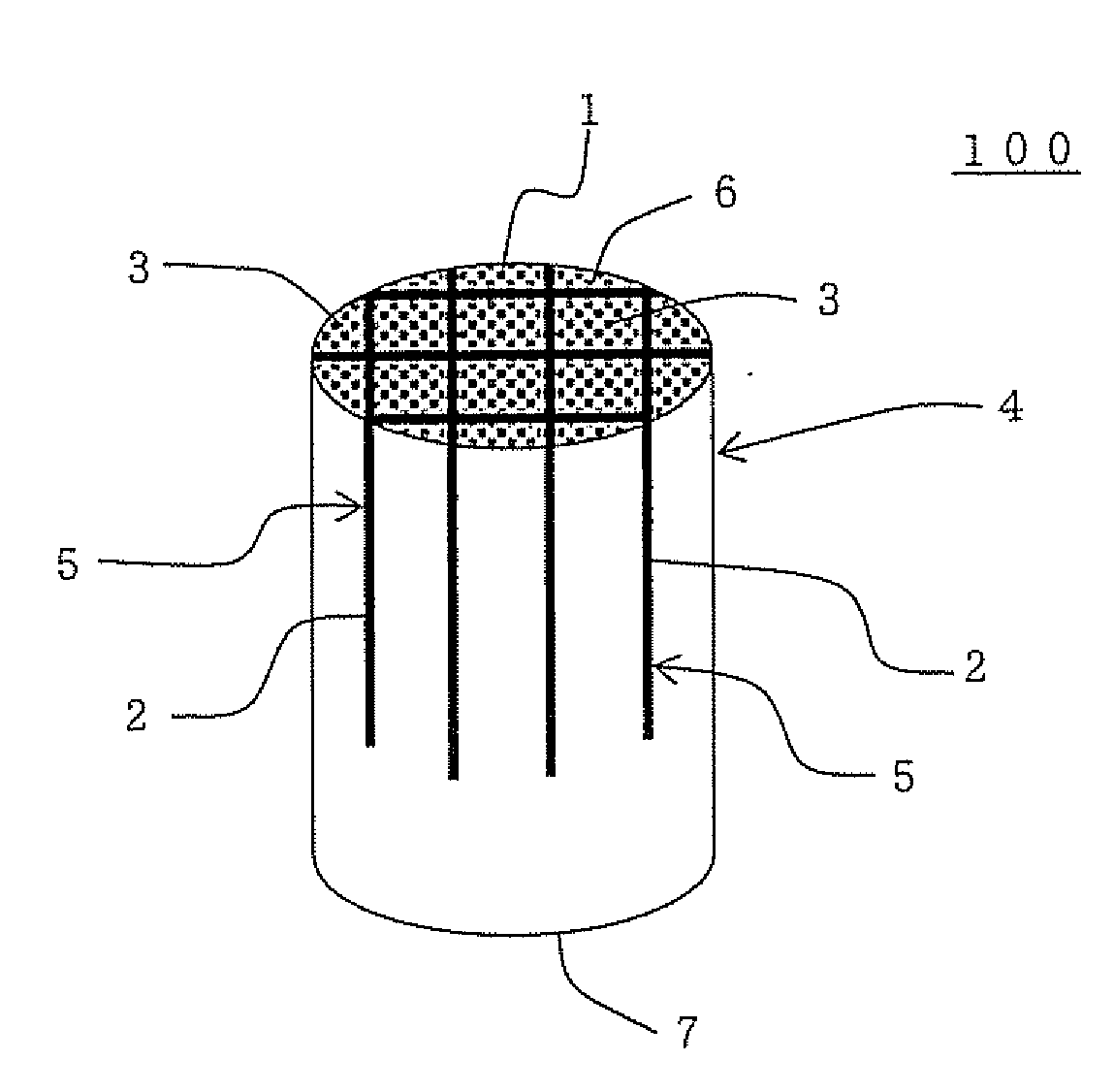
[0095]The cylindrical kneaded clay obtained above was formed into a honeycomb shape by the use of an extruder. After high-frequency dielectric heating-drying, drying was further performed at 120° C. for two hours, followed by cutting both the end faces at a predetermined amount to obtain a cylindrical honeycomb formed article having a partition wall thickness of 310 μm, a cell density of about 46.5 cells / cm2 (300 cells / inch2), a bottom face radius of 145 mm, and a length of 155 mm. Incidentally, the partition wall thickness of the honeycomb formed article was uniform as a whole, and a thick portion was not formed. In addition, the dire...

example 2

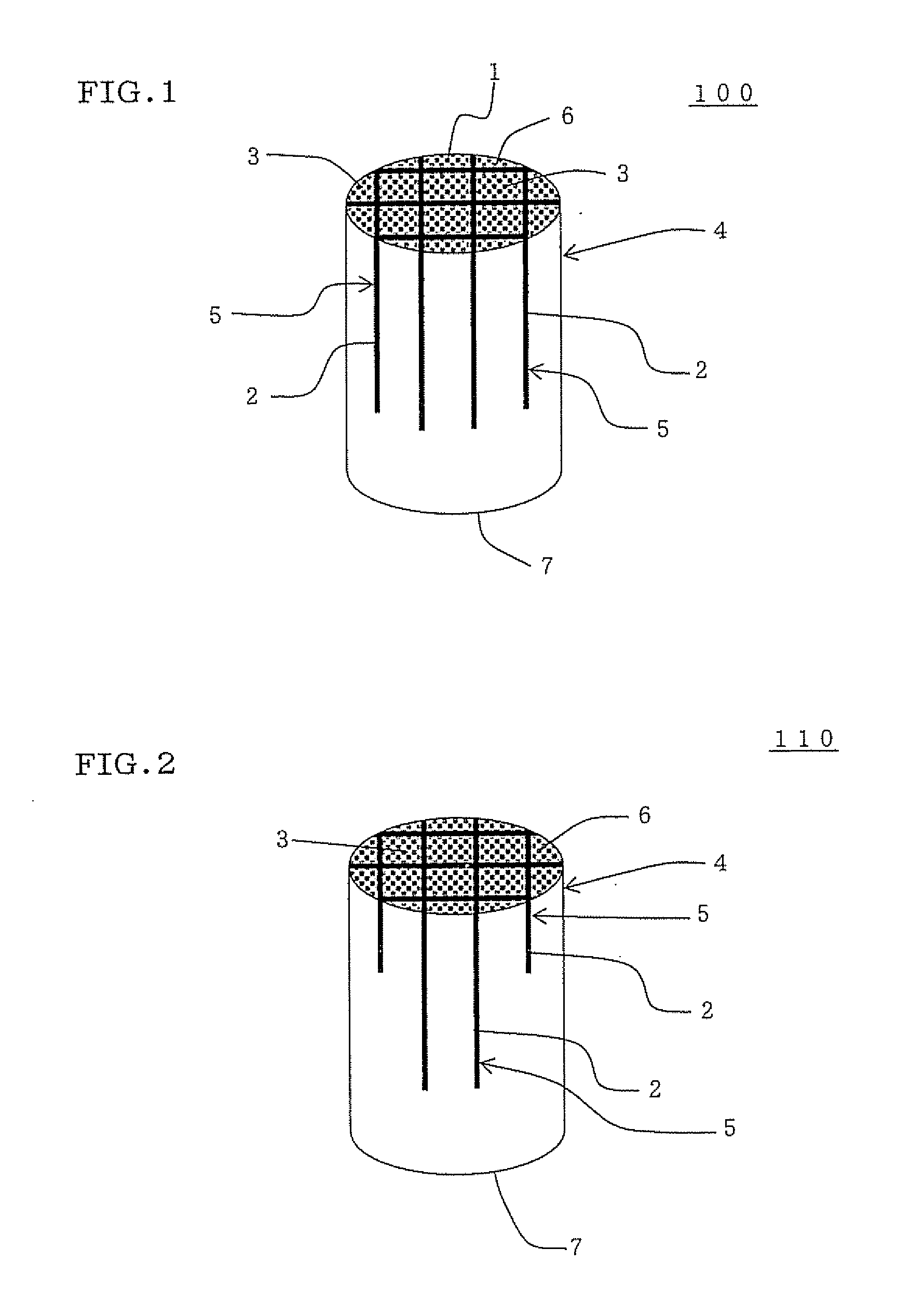
[0104]The honeycomb structure was manufactured in the same manner as in Example 1 except that the slit depth was 50% of the length in the central axial direction of the honeycomb fired article. The honeycomb structure was measured for the regeneration limit (g / liter) and pressure loss (%) in the same manner as in Example 1. The results are shown in Table 1.

example 3

[0105]The honeycomb structure was manufactured in the same manner as in Example 1 except that the slit depth was 75% the length in the central axial direction of the honeycomb fired article. The honeycomb structure was measured for the regeneration limit (g / liter) and pressure loss (%) in the same manner as in Example 1. The results are shown in Table 1.


PUM

PropertyMeasurementUnit
Fractionaaaaaaaaaa
Lengthaaaaaaaaaa
Lengthaaaaaaaaaa

Abstract

A honeycomb structure 100 includes: a honeycomb structured portion 4 having partition walls separating and forming a plurality of cells 1 functioning as fluid passages and extending through from one end face 6 to the other end face 7 and having a plurality of partial segments 3 separated and formed by a plurality of slits 2 extending in a cell extension direction and not reaching at least one of the end faces, and a buffer portions 5 formed by filling a filler in the whole slits 2. The honeycomb structured portion 4 preferably has a plurality of partial segments 3 separated and formed by the plurality of slits 2 extending from the one end face in a cell extension direction and not reaching the other end face 7. The honeycomb structure has excellent thermal shock resistance.

Description

BACKGROUND OF THE INVENTION AND RELATED ART STATEMENT [0001]The present invention relates to a honeycomb structure and a method for manufacturing the honeycomb structure. More specifically, the present invention relates to a honeycomb structure excellent in thermal shock resistance and a method for manufacturing a honeycomb structure, the method capable of manufacturing the honeycomb structure efficiently in good raw material yield.[0002]There is employed a ceramic honeycomb structure excellent in thermal shock resistance and corrosion resistance as a carrier for a catalyst apparatus used for environmental measures, collection of specific substance, or the like, or as a filter in various fields such as chemistry, electric power, and iron and steel. Particularly, in recent years, a honeycomb structure has frequently been employed as a diesel particulate filter (DPF) for trapping particulate matter (PM) discharged from a diesel engine or the like by plugging the opening portions of ce...

Claims


Application Information

Patent Timeline
IPC IPC(8): B32B3/12B29C47/00
CPCB01D46/2429B01D46/2444B01D46/2451Y10T428/24149B01D46/2459B01D46/2466B01D2046/2496B01D46/2455B01D46/2498B01D46/2484B01D46/24494B01D46/2482
Inventor OGURA, YUTAKA
Owner NGK INSULATORS LTD
Learn More