Polycrystalline, magnetic ceramic material, microwave magnetic device, and non-reciprocal circuit device comprising such microwave magnetic device

a microwave magnetic device and non-reciprocal technology, applied in the direction of magnetic materials, magnetic bodies, metallic pattern materials, etc., can solve the problems of inability to produce low-loss, undesired phases, pores, etc., and the requirement of miniaturizing individual devices, etc., to achieve excellent magnetic characteristics

Inactive Publication Date: 2009-10-22
HITACHI METALS LTD
View PDF9 Cites 17 Cited by
  • Summary
  • Abstract
  • Description
  • Claims
  • Application Information

AI Technical Summary

Benefits of technology

[0007]Accordingly, an object of the present invention is to provide a polycrystalline, magnetic ceramic material capable of being simultaneously sintered with silver or copper at a low temperature of 850-1050° C., and having excellent magnetic characteristics.
[0008]Another object of the present invention is to provide a polycrystalline, magnetic ceramic material capable of being simultaneously sintered with silver or copper at a low temperature of 850-1050° C., suffering from little formation of undesired phases even if Bi is contained, having a small ferromagnetic resonance half-width ΔH and dielectric loss (tan δ), and such a temperature coefficient αm as to compensate the temperature characteristics of saturation magnetization 4 πMs of a permanent magnet.

Problems solved by technology

Communications equipments using electromagnetic waves in a microwave band, such as cell phones, satellite broadcasting equipments, etc., have been getting increasingly smaller in recent years, resulting in increasing requirement of miniaturizing individual devices.
However, when Bi or a low-melting point glass is added to a microwave, magnetic material having a narrow single-phase range, undesired phases, pores, etc. are likely to be generated, failing to produce a low-loss, microwave, magnetic body.

Method used


Image

  • Polycrystalline, magnetic ceramic material, microwave magnetic device, and non-reciprocal circuit device comprising such microwave magnetic device
  • Polycrystalline, magnetic ceramic material, microwave magnetic device, and non-reciprocal circuit device comprising such microwave magnetic device
  • Polycrystalline, magnetic ceramic material, microwave magnetic device, and non-reciprocal circuit device comprising such microwave magnetic device

Examples


example 1

[0045]Gd2O3, Y2O3, CaCO3, Bi2O3, Fe2O3, In2O3, V2O5, Al2O3 and ZrO2 each having a purity of 99.0% or more were formulated as starting materials in the composition shown in Table 1, mixed with ion-exchanged water to a slurry concentration of 40% by mass, wet-blended by a ball mill for 40 hours, and then dried. The resultant powder was calcined at a temperature of 825° C. for 2 hours. The calcined powder was mixed with ion-exchanged water to a slurry concentration of 40% by mass, wet-pulverized by a ball mill for 24 hours, and then dried. The resultant magnetic ceramic composition powder had an average particle size of 0.7 μm. This magnetic ceramic composition powder was mixed with an aqueous solution of a binder (PVA), and blended to obtain granulated powder, which was molded to a disc of 14 mm in diameter and 7 mm in thickness at a pressure of 2 ton / cm2. This molding was sintered at the temperature shown in Table 1 for 8 hours in the air.

TABLE 1Main Components (by atomic ratio)Y sit...

example 2

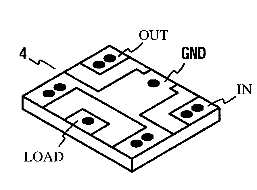
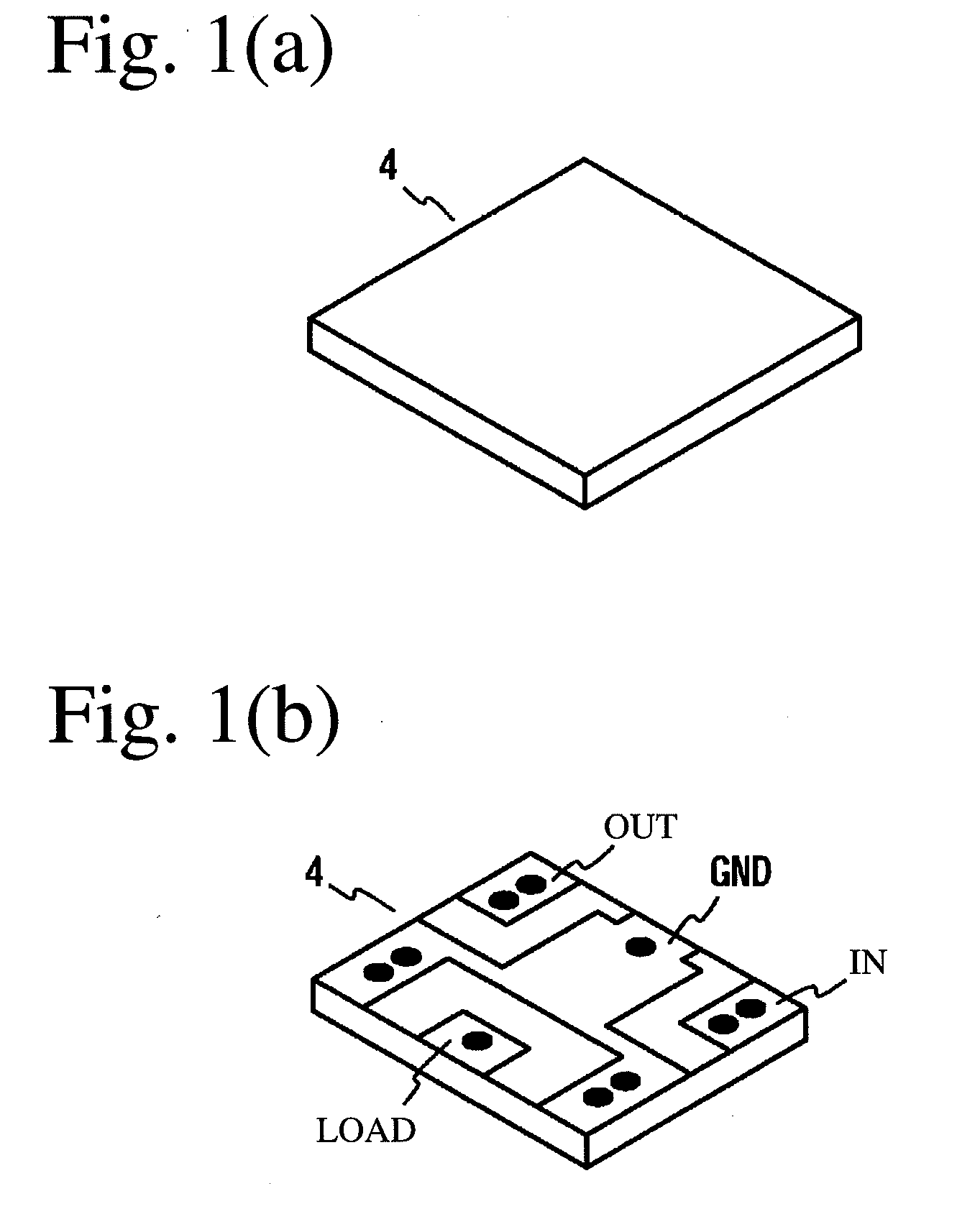
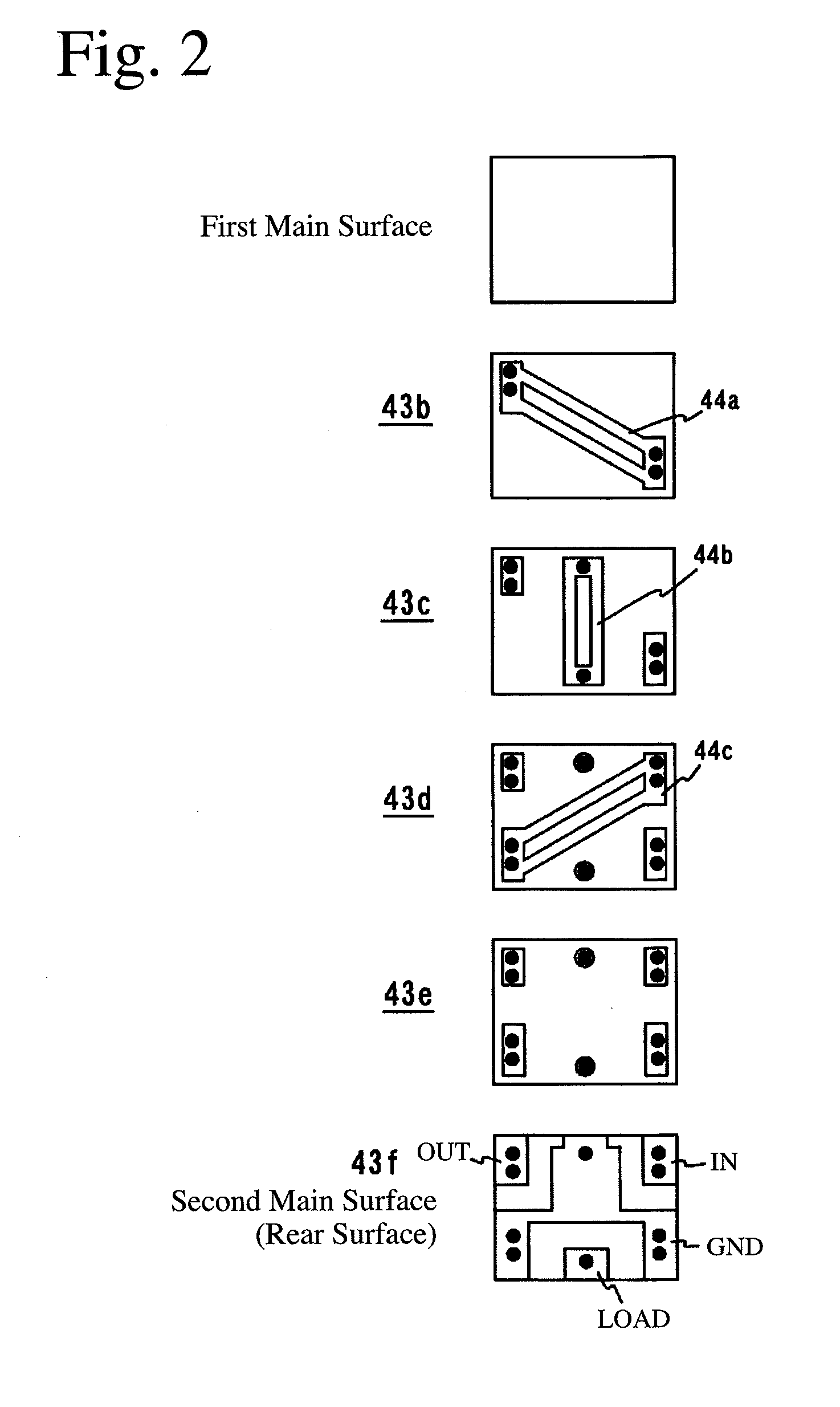
[0049]Central conductors were laminated on a rectangular microwave magnetic body having opposing first and second main surfaces and side surfaces connecting both main surfaces to produce a central conductor assembly 4 having the structure shown in FIGS. 4 and 5 by the following process. First, starting materials comprising Y2O3, Bi2O3, CaCO3, Fe2O3, In2O3, Al2O3 and V2O5 having the composition of Sample No. 20 shown in Table 1 were wet-mixed by a ball mill. The resultant slurry was dried, calcined at a temperature of 850° C., and then wet-pulverized by a ball mill to produce polycrystalline, magnetic ceramic material powder having the formula of (Y1.45Bi0.85Ca0.7)(Fe3.95In0.3Al0.4V0.35)O12 (by atomic ratio). This magnetic material powder was mixed with an organic binder (polyvinyl butyral, PVB), a plasticizer (butylphthalyl butylglycolate, BPBG), and an organic solvent (ethanol and butanol) in a ball mill, adjusted in viscosity, and formed into magnetic ceramic green sheets of 40 μm...


PUM

PropertyMeasurementUnit
saturation magnetizationaaaaaaaaaa
residual magnetic flux densityaaaaaaaaaa
melting pointaaaaaaaaaa

Abstract

A polycrystalline, magnetic ceramic material having a basic composition represented by the general formula of (Y3-x-y-zBiXCayGdz)(Fe5-α-β-γ-εInαAlβVγZrε)O12, wherein 0.4<x≦1.5, 0.5≦y≦1, 0≦z≦0.5, y+z<1.3, 0≦α≦0.6, 0≦β≦0.45, 0.25≦γ≦0.5, 0≦ε≦0.25, and 0.15 ≦α+β≦0.75 each by an atomic ratio, which is predominantly composed of a phase having a garnet structure, and sinterable at a temperature of 850-1050° C.

Description

FIELD OF THE INVENTION[0001]The present invention relates to a microwave, magnetic material used for high-frequency circuit devices, particularly to a polycrystalline, magnetic ceramic material capable of being simultaneously sintered with electrode materials such as silver and copper, etc.BACKGROUND OF THE INVENTION[0002]Communications equipments using electromagnetic waves in a microwave band, such as cell phones, satellite broadcasting equipments, etc., have been getting increasingly smaller in recent years, resulting in increasing requirement of miniaturizing individual devices. Typical high-frequency circuit devices used in communications equipments are microwave, non-reciprocal circuit devices such as circulators, isolators, etc. The isolator does not substantially attenuates signals in a transmitting direction while largely attenuating them in an opposite direction, and is used in transmission / receiving circuits in mobile communications equipments in microwave and UHF bands, ...

Claims


Application Information

Patent Timeline
Patent Type & Authority Applications(United States)
IPC IPC(8): H05K1/09H01F1/00
CPCC04B35/2675C04B2235/3208H01L2924/0002C04B2235/3217C04B2235/3224C04B2235/3225C04B2235/3239C04B2235/3244C04B2235/3286C04B2235/3298C04B2235/5445C04B2235/6025C04B2235/656C04B2235/764H01F1/346H01L23/64H01L25/16H01P1/32H01P1/36H01P1/387H01L2924/00C04B35/26H01F1/34H01P1/383
Inventor NAKAJIMA, HIROKAZUITOH, HIROYUKI
Owner HITACHI METALS LTD
Why Eureka
Try Eureka