Photoresist-free metal deposition

a metal deposition and resist-free technology, applied in the field of photoresist-free metal deposition, can solve the problems of increased processing time, increased processing cost, and increased processing cost, and achieve the effects of reducing or eliminating the associated material and equipment costs, environmental cost, and processing tim

Inactive Publication Date: 2009-11-12
NOVELLUS SYSTEMS
View PDF99 Cites 5 Cited by
  • Summary
  • Abstract
  • Description
  • Claims
  • Application Information

AI Technical Summary

Benefits of technology

[0019]Embodiments in accordance with the invention reduce or eliminate standard repetitive surface patterning processing, such as photoresist processing, thereby reducing or eliminating the associated material and equipment expenses, processing time, and environmental costs.
[0020]Some embodiments in accordance with the invention utilize membrane-mediated elements to achieve electrochemical oxidization and planarization. Membrane-mediated elements also help to avoid well-known terminal effect phenomena (ohmic-resistance current distribution problems in thin metal layers).
[0021]Methods in accordance with the invention allow use of relatively simple, low-cost wet-etching techniques after metal plating that selectively remove remains of metal (e.g., copper) and typicall

Problems solved by technology

As the number of levels in an interconnect technology increases, the stacking of additional layers produces more rugged and complex topography.
Baths with good “bottom-up” filling characteristics fill high aspect ratio features more rapidly and without creating voids or seams when compared to baths with less effective combinations of such additives.
The use of advanced “bottom-up” electrofilling techniques with wafers having low and high aspect-ratio features has created a problem of deposited metal surfaces with a wide range of topography, that is, topography containing a large range or aspect ratios of both recessed and raised areas.
Therefore, while electroplating is the preferred method of metallization, various aspects of improved plating regimens create challenging topography for subsequent planarization
Overburden is undesirable for a number of reasons.
It requires deposition of considerable amounts of excess copper over the field that is essentially wasted andit requires extra effort associated with removing the overburden material.
Thus, overburden represents additional materials costs (excess copper deposited and removed), as well as decreased throughput and productivity.
CMP and eCMP are particularly expensive processes that generally use corrosive chemical and slurry formulations on large (wafer scale or larger) pads to polish the surface of the integrated circuit substrate.
Such pad-rubbing processes are often difficult to control and the polishing end-point can

Method used


Image

  • Photoresist-free metal deposition
  • Photoresist-free metal deposition
  • Photoresist-free metal deposition

Examples


example 1

[0160]An exemplary embodiment of a method of forming a stamp in accordance with the invention suitable for selectively applying a substrate-treating species to a substrate surface is described herein with reference to FIGS. 6B-6E. It is understood that other embodiments in accordance with the invention are suitable for making a stamp.

[0161]A circular piece of blank (unpatterned) nanoporous material having a diameter of about 400 mm is fastened to a flat, circular polymeric support having a diameter of about 330 mm. The nanoporous membrane material is attached to the support by a circular ring that slides down around the outside edge of the circular support. One example of a suitable nanoporous membrane material is NAFION®, commercially available from Dupont. Another is resorcinol formaldehyde aerogel, as described in U.S. Pat. No. 4,873,218, issued Oct. 10, 1989, to Pekala, and in U.S. Pat. No. 4,997,804, issued Mar. 5, 1991, to Pekala, which are hereby incorporated by reference as ...

example 2

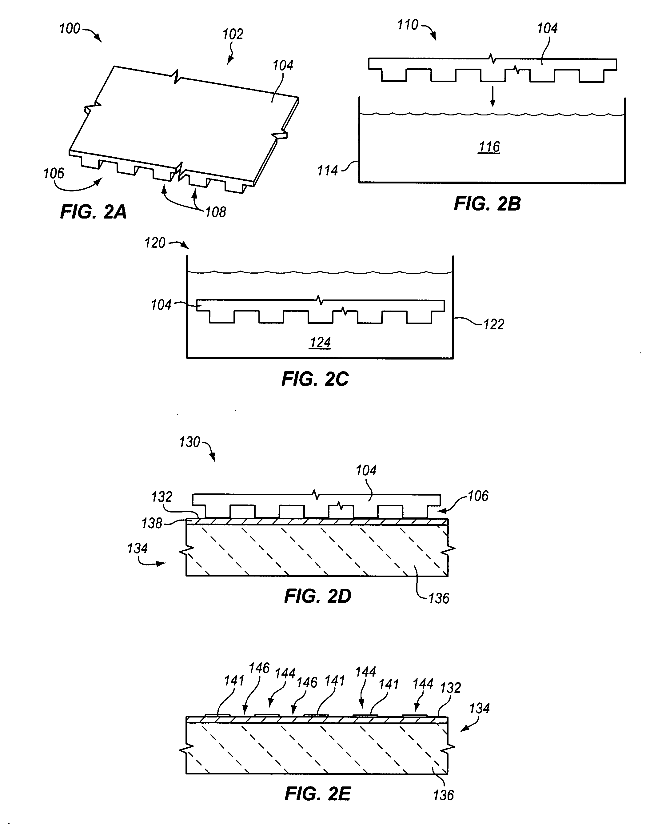
[0163]A 300 mm semiconductor wafer is located face-up on a substrate holder. The wafer comprises a flat base dielectric SiO2 layer covered by a smooth 40 nm copper seed layer. A patterned membrane stamp as described in Example 1 is attached by a circular clamp to a face-down stamping head having a diameter of 330 mm. The material composition of the stamping head is essentially porous polyvinylidene difluoride (PVDF). The stamping head contains an integral liquid reservoir having a total volume of about 200 ml containing 1 g / L MPSA in water accelerator solution. The stamping head is lowered so that the membrane make physical contact with the substrate with a pressure of approximately 1 psi for approximately 2 minutes to form an accelerated pattern region containing accelerator on the substrate (e.g., FIG. 2E).

[0164]Thereafter, the substrate surface is electrochemically plated in a copper plating apparatus for 60 seconds at 15 mA / cm2 in a bath containing 50 ppm dimercaptopropane sulph...

example 3

[0165]A 300 mm semiconductor wafer is located face-up on a substrate holder. The wafer comprises a base dielectric SiO2 layer covered by a 20 mm copper seed layer. A patterned membrane stamp as described in Example 1 is attached by a circular clamp to a face-down stamping head having a diameter of 330 mm, as described in Example 2. The stamping head contains an integral liquid reservoir having a total volume of about 600 ml containing 1 g / L 3-mercapto-1-butanol in water accelerator precursor solution. The stamping head is lowered so that the membrane make physical contact with the substrate with a pressure of approximately 1 psi for approximately 2 minutes to form a treated pattern region containing accelerator precursor on the substrate (e.g., FIG. 2H).

[0166]The accelerator precursor is converted to an active accelerator by converting the alcohol group to a sulfonic acid. This acidification is effected by exposing the substrate surface to 10% sulfuric acid at room temperature for a...


PUM

PropertyMeasurementUnit
Dielectric polarization enthalpyaaaaaaaaaa

Abstract

Selectively accelerated or selectively inhibited metal deposition is performed to form metal structures of an electronic device. A desired pattern of an accelerator or of an inhibitor is applied to the substrate; for example, by stamping the substrate with a patterned stamp or spraying a solution using an inkjet printer. In other embodiments, a global layer of accelerator or inhibitor is applied to a substrate and selectively modified in a desired pattern. Thereafter, selective metal deposition is performed.

Description

RELATED APPLICATIONS[0001]This application is a divisional application, claiming priority under 35 USC §120 and 37 CFR 1.53(b) of co-owned and co-pending U.S. patent application Ser. No. 11 / 827,800, filed Jul. 13, 2007, by Mayer et al., which claims the benefit under 35 USC 119 (e) of U.S. Provisional Application Ser. No. 60 / 832,534, filed Jul. 21, 2006, by Mayer et al., titled “Photoresist-Free Metal Deposition”, and U.S. Provisional Application Ser. No. 60 / 836,711, filed Aug. 9, 2006, by Mayer et al., titled “Photoresist-Free Metal Deposition”.FIELD OF THE INVENTION[0002]The invention relates in general to methods and systems for depositing material in patterns to form structures in electronic equipment, particularly for forming metal features in electronic equipment, and more particularly to the plating of metal wiring in integrated circuits, printed wiring boards and semiconductor packaging as well as to creating relevant structures for micro- and nano- electro-mechanical system...

Claims


Application Information

Patent Timeline
IPC IPC(8): B23H3/00B05D3/00C25B9/00
CPCC25F5/00H05K3/07H05K3/108C25D5/022H05K2203/0392H05K2203/0537H05K2203/0713H05K2203/0108
Inventor MAYER, STEVEN T.DREWERY, JOHN STEPHENWEBB, ERIC G.
Owner NOVELLUS SYSTEMS
Why Eureka
Try Eureka