
Nanocrystalline Composite for Storage of Hydrogen

a technology of nanocrystalline composites and hydrogen, which is applied in the direction of transportation and packaging, coatings, other chemical processes, etc., can solve the problems of limiting the advantages of such a material and the relatively high cost of vanadium, and achieve the effect of improving the absorption and desorption kinetics

Active Publication Date: 2009-11-12
CENT NAT DE LA RECHERCHE SCI
View PDF6 Cites 14 Cited by
  • Summary
  • Abstract
  • Description
  • Claims
  • Application Information

AI Technical Summary

Benefits of technology

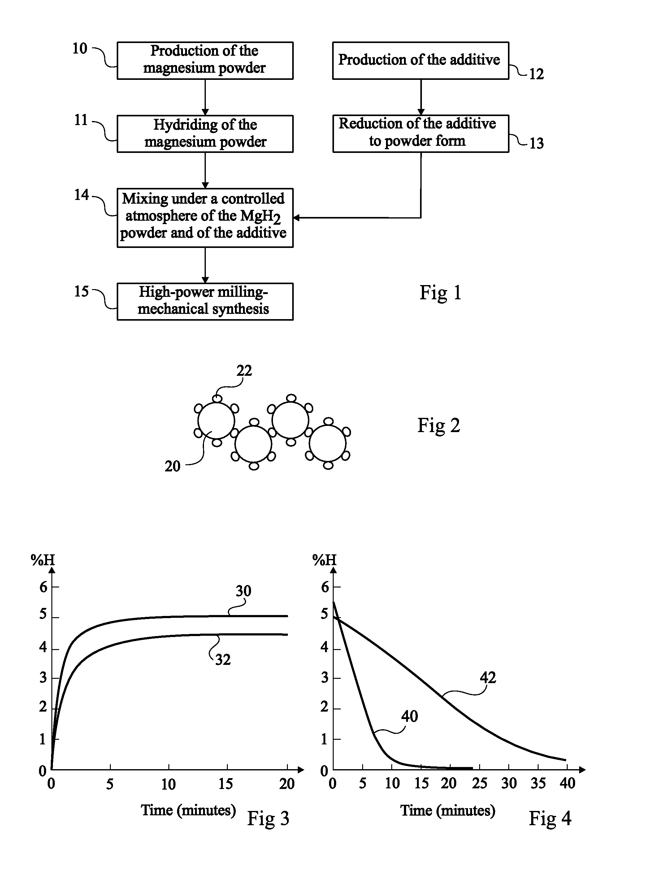
[0008]The present invention aims at obtaining a compound material for the storage of hydrogen, which is based on magnesium and has improved absorption and desorption kinetics and a reversible storage capacity which is at least equivalent to that of known magnesium-based hydrogen storage materials.
[0010]According to another aim of the present invention, the method is simple and likely to be implemented conventionally, in the same way as for activated magnesium compound materials.

Problems solved by technology

However, for pure magnesium, acceptable absorption and desorption kinetics are only obtained for temperatures greater than 300° C., which limits the advantages of such a material.
Further, vanadium is a relatively expensive material.

Method used


Image

  • Nanocrystalline Composite for Storage of Hydrogen
  • Nanocrystalline Composite for Storage of Hydrogen

Examples


first embodiment

[0021]According to the invention, the additive corresponds to an alloy (a1) of body-centered crystal structure, based on titanium (Ti), on vanadium (V), and on another material preferentially selected from among chromium (Cr) and / or manganese (Mn). The alloy (a1) may be of single-phase type (alloy of defined intermetallic compound type) or of multiphase type. Of course, the alloy (a1) may contain other elements in minor proportions.

[0022]According to the first embodiment of the invention, the alloy (a1) complies with the following general formula:

TiaVbMcM′d

where

[0023]M designates chromium, manganese, or a chromium and manganese alloy;

[0024]M′ designates a metal or an alloy of metals, other than Ti, V, Cr, or Mn, for example selected from among iron, cobalt, nickel, or mixtures of these metals;

[0025]a is a number in the range 0.05 to 2.5, typically between 0.1 and 2, for example, between 0.2 and 1.5;

[0026]b is a number in the range 0.05 to 2.9, typically between 0.1 and 2.2;

[0027]c i...

second embodiment

[0048]According to the invention, the additive is obtained by co-fusion followed by a cooling of the following metal mixtures, or by carrying out a mechanosynthesis step by co-milling of the following metal mixtures:

[0049]a first alloy or metal mixture (m1) which may correspond to the first alloy (a1) or to a mixture of the metals forming said alloy (a1), in the proportions of said alloy, these metals being present in the mixture as simple metals (non-alloyed) and / or as metal alloys; and

[0050]a second alloy or mixture (m2), which is[0051]an alloy (a2) comprising:[0052]from 38 to 42 mol % of a first metal M1 selected from among zirconium (Zr), niobium (Nb), molybdenum (Mo), hafnium (Hf), tantalum (Ta), tungsten (W), and mixtures of these metals; and[0053]from 56 to 60 mol % of a second metal M2 selected from among nickel (Ni), copper (Cu), and alloys or mixtures of these metals; or[0054]a mixture of the metals forming said alloy (a2), in the proportions of said alloy, these metals be...


PUM

PropertyMeasurementUnit
diameteraaaaaaaaaa
diameteraaaaaaaaaa
diameteraaaaaaaaaa

Abstract

The invention relates to a method for preparation of a material adapted to reversible storage of hydrogen, including steps consisting of providing a first powder of a magnesium-based material, hydrogenating the first powder to convert at least part of the first powder into metal hydrides, mixing the first hydrogenating powder with a second powder additive, the proportion by mass of the second powder in the mix obtained being between 1% and 20% by mass, wherein the additive is formed from an alloy with a centred cubic structure based on titatnium, vanadium and at least one other metal chosen from chromium or manganese, and grinding the mix of first and second powders.

Description

FIELD OF THE INVENTION[0001]The present invention relates to materials used for the reversible storage of hydrogen. More specifically, the present invention relates to magnesium-based materials used for the combined storage of hydrogen. The present invention also relates to methods for preparing such materials.DISCUSSION OF PRIOR ART[0002]Hydrogen (H2) is used in many industrial fields, especially as fuel (for example, in heat engine or fuel cells), or again as a reactant (for example, for hydrogenation reactions). In this context, due to its volume in gaseous state and to its explosibility, it is desirable for hydrogen to be stored in a form ensuring a low bulk and a secure confinement.[0003]A possibility is to store hydrogen in the form of metal hydrides. In this case, the hydrogen to be stored is put in contact with a metal or a metal alloy under pressure and temperature conditions which induce an incorporation of the hydrogen in atomic form into the crystal lattice (absorption r...

Claims


Application Information

Patent Timeline
Patent Type & Authority Applications(United States)
IPC IPC(8): C09K3/00
CPCB22F9/04Y10S420/90B22F2998/10B22F2999/00C01B3/0031C01B3/0078C22C1/0408C22C14/00C22C27/025C22C27/06Y02E60/327B22F2998/00B22F1/0088B22F2201/013B22F1/0003B22F1/025Y02E60/32F17C11/005B22F1/145B22F1/17B22F1/12
Inventor FRUCHART, DANIELDE RANGO, PATRICIACHARBONNIER, JEANMIRAGLIA, SALVATORERIVOIRARD, SOPHIESKRYABINA, NATALIYAJEHAN, MICHEL
Owner CENT NAT DE LA RECHERCHE SCI
Learn More