Protective material and image forming apparatus using the protective material

a technology of protective materials and image forming apparatus, which is applied in the direction of carpet cleaners, instruments, vehicles, etc., can solve the problems of deterioration of image resolution, shortening of life, and production of poor quality images, and achieves the effect of high resistivity of charging rollers

Active Publication Date: 2009-11-12
RICOH KK
View PDF3 Cites 42 Cited by
  • Summary
  • Abstract
  • Description
  • Claims
  • Application Information

AI Technical Summary

Benefits of technology

[0024]Accordingly, an object of the present invention is to provide a protective material block protecting a photoreceptor even when rotating at high speed and capable of producing high-quality images without black stripes due to high resistivity of a charging roller.

Problems solved by technology

However, since the cleaning blade is pressed to the surface of a photoreceptor to remove residues thereon, a stress due to friction between the surface of a photoreceptor and the cleaning blade is large and the cleaning blade and the photoreceptor, particularly an organic photoreceptor, are abraded, resulting in shorter lives thereof.
Particularly when the cleaning blade has insufficient dimensional accuracy, assemble accuracy or partially oscillates, the toner scrapes through the blade more, resulting in production of poor quality images.
A toner is likely to adhere to the photoreceptor in the form of a film with a fatty acid, resulting in deterioration of image resolution, abrasion of the photoreceptor and uneven image density.
Since the thus prepared metal soap block has an isotropic and precise crystal, the durability of a brush is not sufficient because of being pressed to the metal soap at higher pressure to apply a large amount of the metal soap to a photoreceptor having a high linear speed.
When the metal soap is fixed on the charging roller, the metal soap involves a toner present on a photoreceptor and a part of the charging roller the metal soap is fixed on has high resistivity, resulting in defective charging and production of images having black stripes.
However, as shown in FIG. 4 in Japanese published unexamined application No. 2007-140391, particulate metal soaps having various sizes are present.
Namely, when the amount of the metal soap applied to a photoreceptor varies, particularly when it decreases, the blade having high hardness gives a large stress thereto, resulting in scratches thereof and abrasion of the blade.
However, the scraped metal soaps still have various sizes and are not necessarily applied to a photoreceptor in the width direction.
However, since additional members such as a metal soap oscillator, a cutter and a thermodetector are needed to stabilize an amount of the metal soap block applying to a photoreceptor, the mechanism and control are complicated.
However, this does not consider at all the size of the scraped particulate metal soap and resolve positional unevenness of the amount of the metal soap block applying thereto.

Method used


Image

  • Protective material and image forming apparatus using the protective material
  • Protective material and image forming apparatus using the protective material
  • Protective material and image forming apparatus using the protective material

Examples


examples

Protective Material Block 1 (Comparative Example)

[0323]Zinc stearate was heated at 145° C. to be melted in a mold, and cooled to prepare a protective material block 1 having a depth of 40 mm, a width of 8 mm and a length of 350 mm.

Protective Material Block 2 (Example)

[0324]65 parts of stearic acid and 35 parts of palmitic acid were mixed to prepare a mixture. Zinc hydroxide was mixed with the mixture and dried to prepare particles including compatibilized zinc stearate and zinc palmitate and having a diameter of from 25 to 33 μm. The particles were partially dissolved in hydrochloric acid-methanol solution and heated at 80° C. to methylate the stearic acid and the palmitic acid. A ratio of the zinc stearate to the zinc palmitate was measured by gas chromatography. The weight ratio was 64 / 34.

[0325]The particles were placed in a compression mold and an ultrasonic vibration was applied thereto to uniformly disperse them therein. The particles were compressed from above until they have ...

examples 3 to 7

[0349]The image forming apparatus used in Example 1 was modified such that the photoreceptor had a linear speed of 220 mm / sec. 3. A DC voltage of −600 V overlapped with an AC voltage having a frequency of 1.9 kHz and an amplitude of 1.2 kV was applied to the photoreceptor from the charging roller.

[0350]Each four process cartridges using the photoreceptor 2 and the protective material blocks 6 to 11 were prepared and installed in the modified tandem image forming apparatus. Five by five, 30,000 images of a test chart having an image area of 5% were produced totally at 27° C. and 45% RH. Then, halftone yellow, cyan, magenta and black images were produced to evaluate them. The image forming apparatus using the protective material block 6 produced black images on which slight abnormal stripes were observed although acceptable. The image forming apparatus using the protective material blocks 7 to 10 produced high-quality halftone images of all the colors. The image forming apparatus usin...

examples 8 to 10

[0352]The image forming apparatus used in Example 1 was modified such that the photoreceptor had a linear speed of 220 mm / sec. 3. A DC voltage of −600 V overlapped with an AC voltage having a frequency of 1.9 kHz and an amplitude of 1.2 kV was applied to the photoreceptor from the charging roller.

[0353]Each four process cartridges using the photoreceptor 2 and the protective material blocks 12 to 14 were prepared and installed in the modified tandem image forming apparatus. Five by five, 15,000 images of a test chart having an image area of 5% were produced totally at 15° C. and 25% RH. Then, halftone yellow, cyan, magenta and black images were produced to evaluate them. The image forming apparatus using the protective material blocks 12 to 14 produced high-quality halftone images of all the colors.

Photoreceptor 3

[0354]An undercoat coating liquid, a charge generation coating liquid and charge transport coating liquid, which have the following formulations, were coated and dried in t...


PUM

PropertyMeasurementUnit
areaaaaaaaaaaa
number-average particle diameter Daaaaaaaaaaa

Abstract

A protective material block including a metal soap, wherein the surface of the protective material block has an X-ray diffraction pattern wherein a ratio (P2 / P1) of a maximum peak height (P2) on a surface separation of from 3.6 to 5.0 Å to a maximum peak height (P1) on a surface separation of from 11 to 16 Å not greater than 0.5.

Description

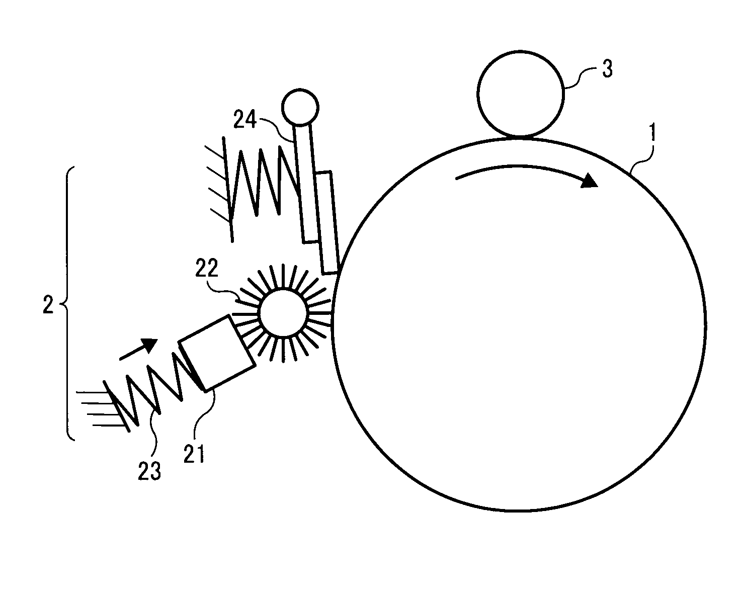
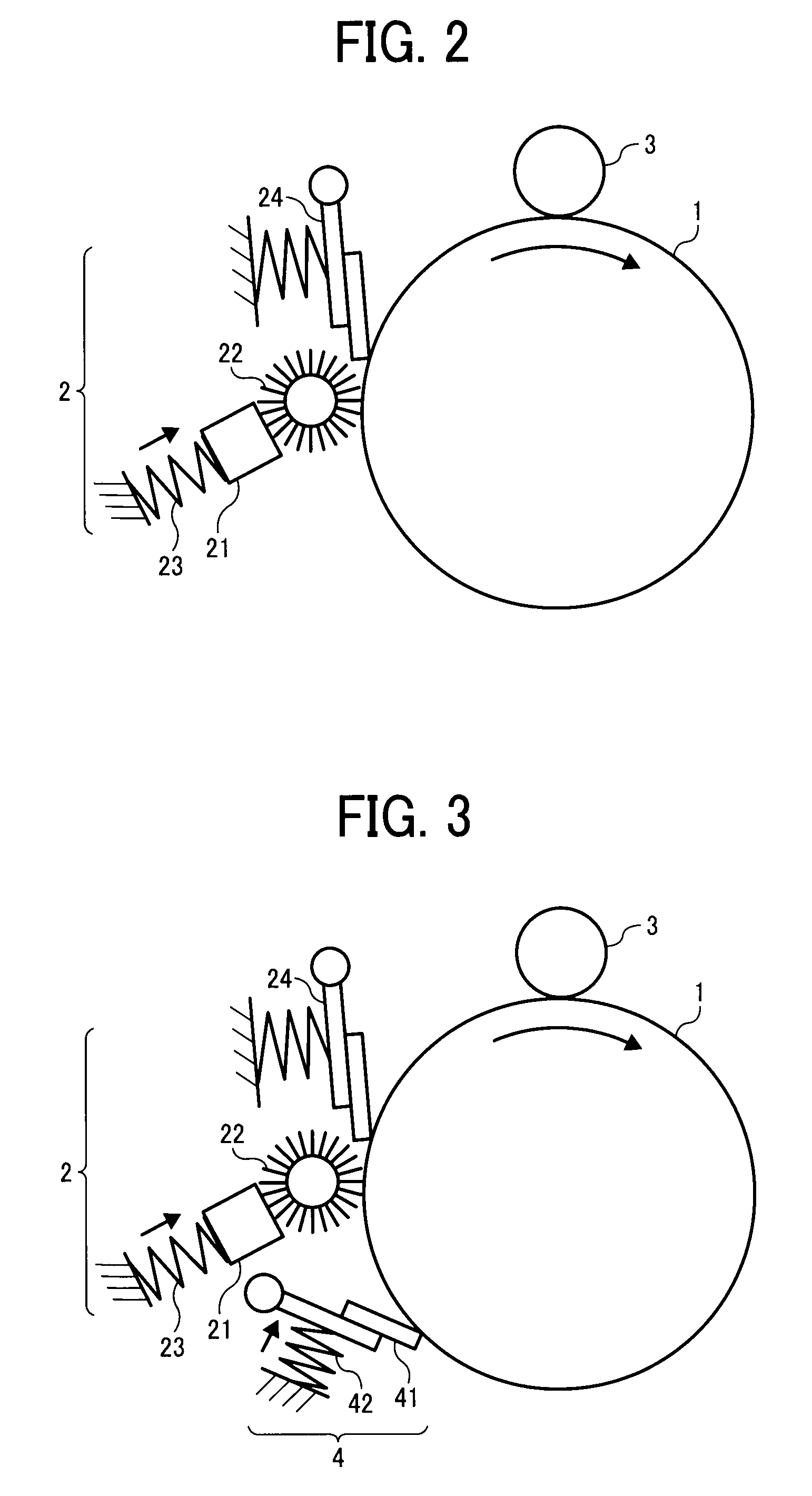
BACKGROUND OF THE INVENTION[0001]1. Field of the Invention[0002]The present invention relates to a protective material protecting the surface of a photoreceptor used for electrophotographic image forming and an image forming apparatus using the protective material.[0003]2. Discussion of the Background[0004]In an electrophotographic image forming apparatus, an image bearer such as a photoconductive photoreceptors is subjected to a charging process, an irradiating process, a developing process and transferring process to form an image. Discharge products produced in the charging process, remaining on the surface of the photoreceptor and residual toners or toner components remaining thereon after the transferring process are removed in a cleaning process.[0005]Conventional cleaning methods use an inexpensive and simple cleaning blade formed of a rubber or urethane, having good cleanability. However, since the cleaning blade is pressed to the surface of a photoreceptor to remove residue...

Claims


Application Information

Patent Timeline
Patent Type & Authority Applications(United States)
IPC IPC(8): G03G21/00
CPCG03G21/0094
Inventor KABATA, TOSHIYUKIHATAKEYAMA, KUMIKOHASEGAWA, KUNIOTANAKA, SHINYAYAMASHITA, MASAHIDEIIO, MASATONAKAI, HIROSHI
Owner RICOH KK
Why Eureka
Try Eureka