Eureka AIR delivers breakthrough ideas for toughest innovation challenges, trusted by R&D personnel around the world.

Method of preparing cathode containing Iron disulfide for a lithium cell

a lithium cell and cathode technology, applied in the field of lithium primary cells, can solve the problems of losing all or a substantial amount of its electrochemical capacity, and achieve the effect of improving the overall efficiency of cathode discharge and using electrical energy

Active Publication Date: 2009-11-26
DURACELL U S OPERATIONS
View PDF26 Cites 29 Cited by
  • Summary
  • Abstract
  • Description
  • Claims
  • Application Information

AI Technical Summary

Benefits of technology

[0021]The invention is directed to lithium primary cells wherein the anode comprises lithium metal. The lithium may be alloyed with small amounts of other metal, for example aluminum, which typically comprises less than about 1 or 2 wt. % of the lithium alloy but may be as high as 5 wt % of the lithium. The lithium which forms the anode active material, is preferably in the form of a thin foil. The cell has a cathode comprising the cathode active material iron disulfide (FeS2), commonly known as “pyrite”. The cathode may also include another coactive material, preferably iron sulfide (FeS) coactive material which is compatible with FeS2. Each cathode coactive material must be dischargeable, that is, must participate in useful electrochemical reaction in order to produce useful electrical energy when the cell is used in normal service. By compatible cathode coactive material is meant that it does not react directly with FeS2 or other coactive materials in direct oxidation-reduction or other reaction, thus losing all or a substantial amount of its electrochemical capacity. If a coactive material is added to the FeS2 cathode mixture it should be stable in the electrolyte and not react with any of the cathode additives or cathode current collector or any other of the cell components. All of the cathode coactive materials should have same or similar OCV (open circuit voltage) within about 10 percent. The OCV of each cathode coactive material against the lithium anode desirably should be between about 1.7 and 1.8 volts so that it is closely compatible with FeS2, which has an OCV (fresh) of about 1.75 volt. In the lithium cell the cathode containing FeS2 and a coactive material should exhibit a similar load voltage profile as the same cell with only FeS2 as cathode active material (within about 10 percent) when the cell is discharged against the same load. The iron sulfide (FeS) has a specific theoretical capacity of 609.8 mAmp-hr / gram, which is lower than the specific theoretical capacity of FeS2 which is 893.6 mAmp-hr / gram. However, as indicated in commonly assigned U.S. patent application Ser. No. 12 / 148,030, the addition of FeS to the FeS2 cathode may improve the overall efficiency of discharge of the cathode particularly at high rate discharge conditions.
[0045]In an aspect of the invention the cathode slurry employing the above indicated hydronaphthalene solvents is prepared and coated onto the substrate, typically a sheet of aluminum, to form the wet cathode composite sheeting as above stated. The cathode composite sheeting is then passed through drying oven preferably employing forced hot air as the drying medium. Preferably the oven has two or more separate zones therein wherein each zone is maintained at a progressively higher temperature in the direction of passage of the wet cathode composite sheeting. The heated air passing through the oven is typically between about 75 and 140° C. Preferably the oven has three heating zones. The first zone is maintained, desirably at a temperature between about 60 and 80° C., typically at about 75° C., the second zone may be maintained at a temperature between about 75 and 105° C., typically at about 95° C., and the third zone may be maintained at a temperature between about 130 and 140° C., typically at about 135° C. The total drying residence time of the wet cathode composite sheet passing through such three zone oven may typically be between about 2.3 and 3.8 minutes. The dry cathode coating on the substrate may then be subjected to calendering to compress the coating thickness. If the dry cathode composite sheeting is to be used at part of a wound electrode assembly, for example, for insertion into a cylindrical housing, it is preferred to prepare the cathode composite sheeting with a cathode coating on each side of the substrate. In this latter case, the final dry cathode composite sheeting may have a total thickness typically between about 0.170 and 0.186 mm. A desirable substrate may be of aluminum having a thickness typically of between about 0.015 and 0.040 mm. The cathode composite sheeting produced in this manner using the above indicated hydronaphthalene solvents and a drying protocol results in a dry cathode coating which resists cracking. Also the preferred solvents (1,2,3,4-tetrahydronaphthalene or decahydronaphthalene) in addition to being extremely good solvents for the styrene-ethylene / butylenes-styrene block copolymer binder, thus forming a good binder / solvent solution. The binder / solvent solution appears also to have strong surface affinity for the FeS2 (or FeS2 and FeS particles). This prevents any prolonged direct exposure of the FeS2 (or FeS2 plus FeS particles) with the drying air or any moisture contained therein and thus reduces the chance of acidic contaminants, such as sulfuric acid forming on the surface of these particles during the drying process.

Problems solved by technology

By compatible cathode coactive material is meant that it does not react directly with FeS2 or other coactive materials in direct oxidation-reduction or other reaction, thus losing all or a substantial amount of its electrochemical capacity.

Method used


Image

  • Method of preparing cathode containing Iron disulfide for a lithium cell
  • Method of preparing cathode containing Iron disulfide for a lithium cell
  • Method of preparing cathode containing Iron disulfide for a lithium cell

Examples


Embodiment Construction

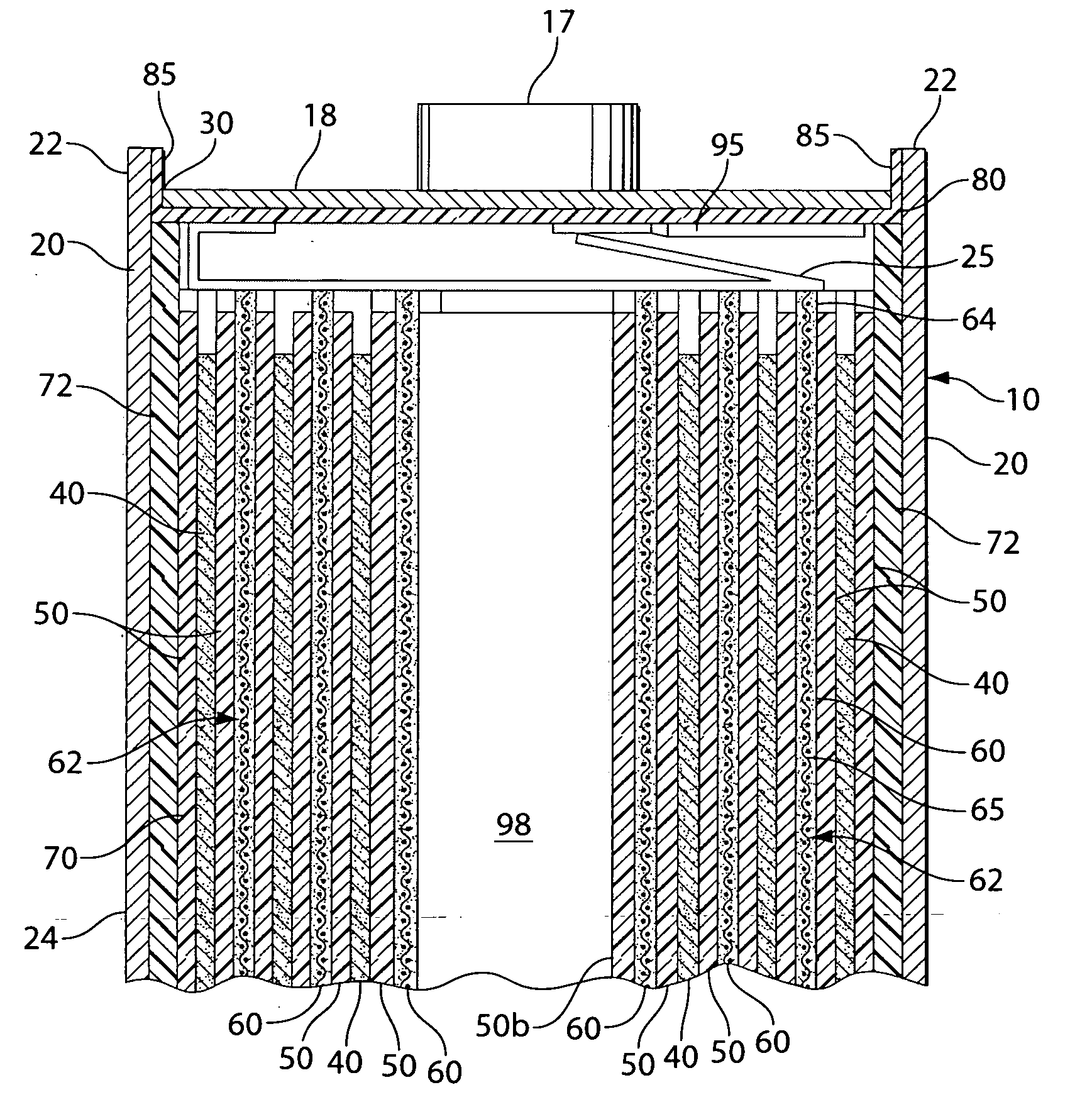
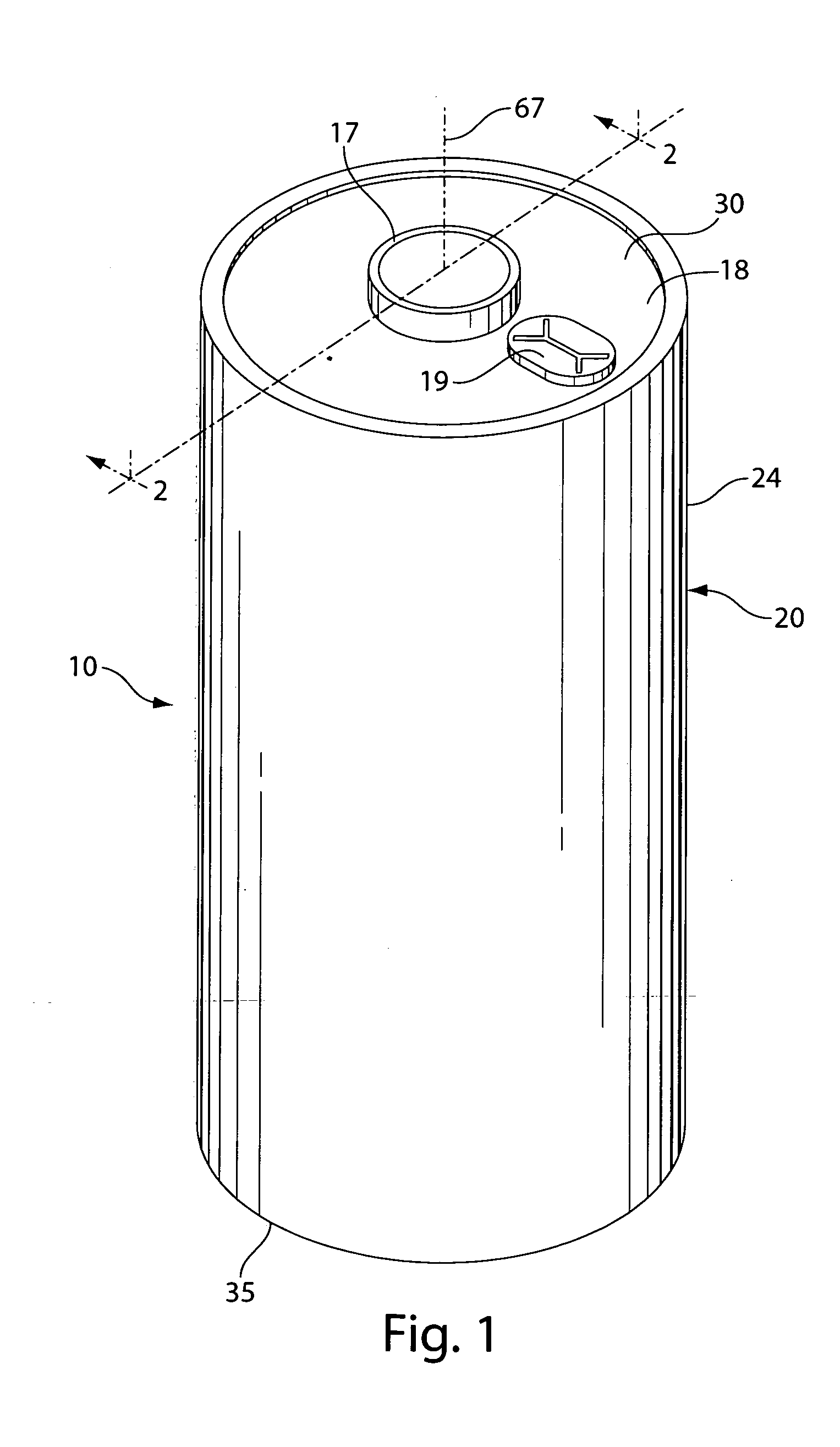
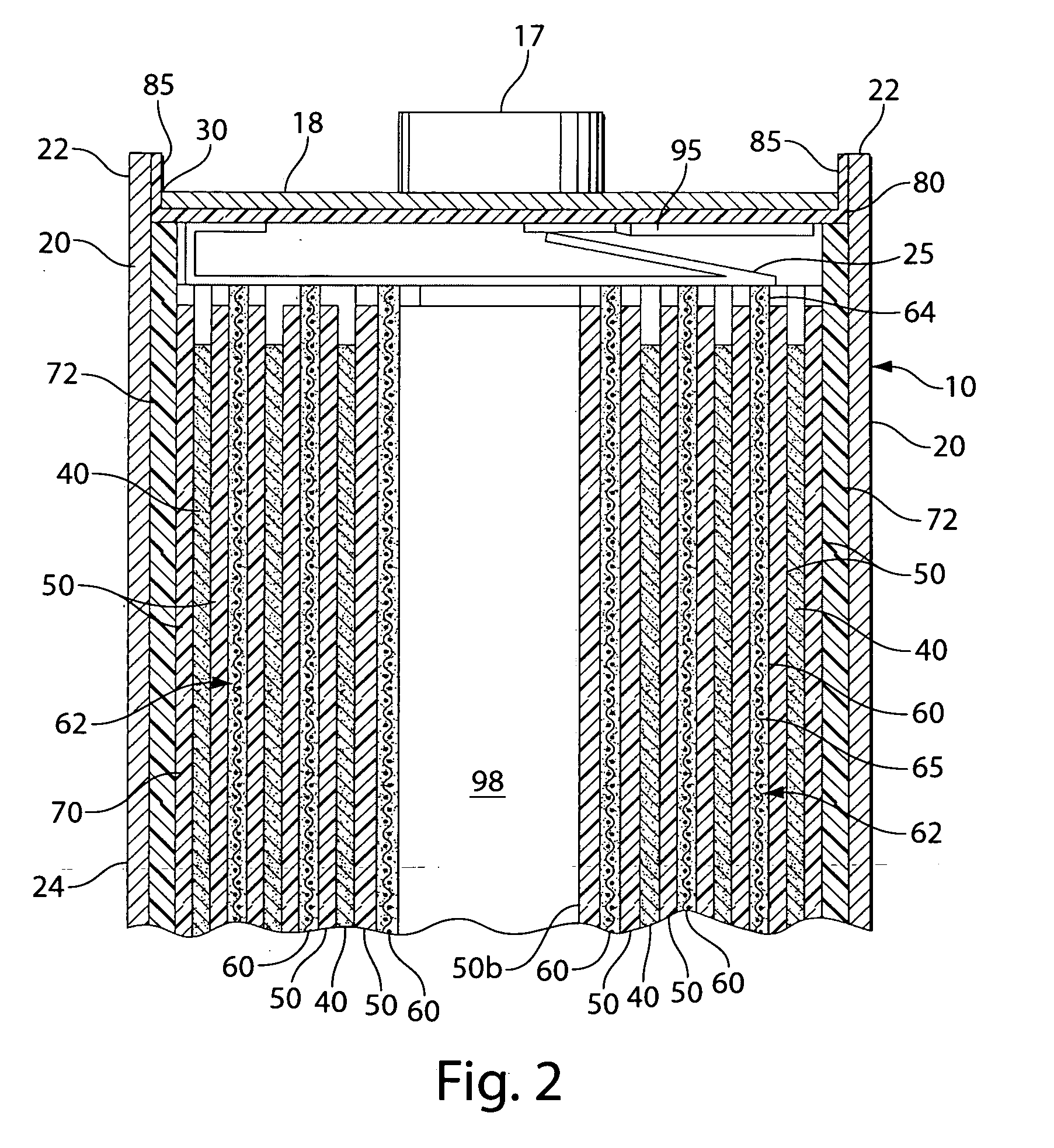
[0054]The cell 10 shown in FIG. 1 may be lithium cell having a cathode comprising FeS2, that is, a Li / FeS2 cell or cell 10 may be a lithium cell having a cathode comprising FeS2+FeS, that is, a Li / (FeS2+FeS) cell. Representative cell 10 may be in the form of a spirally wound cell cylindrical cell as shown in FIG. 1. A wound cell 10 configuration comprising a lithium anode 40 and a cathode composite sheet 62 with separator 50 between the anode 40 and cathode composite sheet 62 is shown in FIG. 2. The cathode composite sheet 62 has a cathode coating 60 comprising FeS2 (or FeS2 plus FeS active material) coated typically on both sides of a substrate 65.

[0055]The cell 10 internal configuration employing FeS2 or FeS2 plus FeS in the cathode, apart from the difference in cathode composition, may be similar to the spirally wound configuration shown and described in U.S. Pat. No. 6,443,999. The anode sheet 40 as shown in the figures comprises lithium metal and the cathode sheet 60 comprises ...


PUM

PropertyMeasurementUnit
thicknessaaaaaaaaaa
thicknessaaaaaaaaaa
temperatureaaaaaaaaaa

Abstract

A primary cell having an anode comprising lithium or lithium alloy and a cathode comprising iron disulfide (FeS2) or a mixture of iron disulfide (FeS2) and iron sulfide (FeS) and conductive carbon particles. A cathode slurry is prepared comprising the FeS2 or FeS2 plus FeS powder, conductive carbon, binder, and a solvent. The binder is preferably a styrene-ethylene / butylene-styrene (SEBS) block copolymer. There is an advantage discovered in utilizing a hydronaphthalene solvent to form the cathode slurry. The preferred solvent is 1,2,3,4-tetrahydronaphthalene or decahydronaphthalene and mixtures thereof. The slurry mixture is coated onto a conductive substrate and the solvent evaporated leaving a dry cathode coating on the substrate. Higher drying temperature may be used resulting in a dry cathode coating which resists cracking. The anode and cathode can be spirally wound with separator therebetween and inserted into the cell casing with electrolyte then added.

Description

FIELD OF THE INVENTION[0001]The invention relates to lithium primary cells having an anode comprising lithium and a cathode comprising iron disulfide (FeS2) and a method of preparing the cathode for such cells.BACKGROUND[0002]Primary (non-rechargeable) electrochemical cells having an anode of lithium are known and are in widespread commercial use. The anode is comprised essentially of lithium metal. Such cells typically have a cathode comprising manganese dioxide, and electrolyte comprising a lithium salt such as lithium trifluoromethane sulfonate (LiCF3SO3) dissolved in an organic solvent. The cells are referenced in the art as primary lithium cells (primary Li / MnO2 cells) and are generally not intended to be rechargeable. Alternative, primary lithium cells with lithium metal anodes but having different cathodes, are also known. Such cells, for example, have cathodes comprising iron disulfide (FeS2) and are designated Li / FeS2 cells. The iron disulfide (FeS2) is also known as pyrite...

Claims


Application Information

Patent Timeline
Patent Type & Authority Applications(United States)
IPC IPC(8): H01M4/40H01M4/08H01M4/58
CPCH01M4/1397H01M4/5815H01M4/622H01M4/136Y02E60/122H01M4/248H01M6/16Y02E60/10Y02P70/50
Inventor STEVANOVIC, MAYAPOZIN, MICHAELKOUZNETSOVA, YELENASPECHT, STEVEN J.BERKOWITZ, FRED J.
Owner DURACELL U S OPERATIONS
Why Eureka
Eureka Blog
Learn More