Novel organic electroluminescent compounds and organic electroluminescent device using the same

Inactive Publication Date: 2009-12-03
GRACEL DISPLAY INC
View PDF20 Cites 8 Cited by
  • Summary
  • Abstract
  • Description
  • Claims
  • Application Information

AI Technical Summary

Benefits of technology

[0007]With intensive efforts to overcome the problems of conventional techniques as described above, the present inventors have researched for developing novel organic electroluminescent compounds to realize an organic EL device having excellent luminous efficiency and surprisingly improved lifetime. Eventually

Problems solved by technology

However, the iridium complex is still construed as a material which is merely applicable to small displays because they cannot provide pure red color and high lumino

Method used


Image

  • Novel organic electroluminescent compounds and organic electroluminescent device using the same
  • Novel organic electroluminescent compounds and organic electroluminescent device using the same
  • Novel organic electroluminescent compounds and organic electroluminescent device using the same

Examples


Example

Preparation Example 1

Preparation of Compound (I)

[0135]

[0136]Preparation of Compound (A)

[0137]To ethanol (100 mL), added were 2-aminonaphthalene-3-aldehyde (5.0 g, 29.2 mmol), acetophenone (4.1 mL, 35.1 mmol), potassium hydroxide (3.3 g, 58.4 mmol), and the mixture was stirred under reflux under argon atmosphere. When the reaction was completed, the reaction mixture was cooled to room temperature. After adding aqueous ammonium hydroxide solution thereto, the resultant mixture was extracted with chloromethane. The extract was filtered under reduced pressure. Purification via column chromatography gave Compound (A) (4.8 g, 64%).

[0138]Preparation of Compound (B)

[0139]Compound (A) (4.0 g, 15.7 mmol) and iridium chloride (2.1 g, 7.1 mmol) were dissolved in 2-ethoxyethanol (38 mL) and distilled water (13 mL), and the solution was stirred under reflux under argon atmosphere for 24 hours. When the reaction was completed, the reaction mixture was cooled to room temperature. The solid produced...

Example

Example 1

Manufacture of an OLED (1)

[0143]An OLED device was manufactured by using a red phosphorescent compound according to the invention.

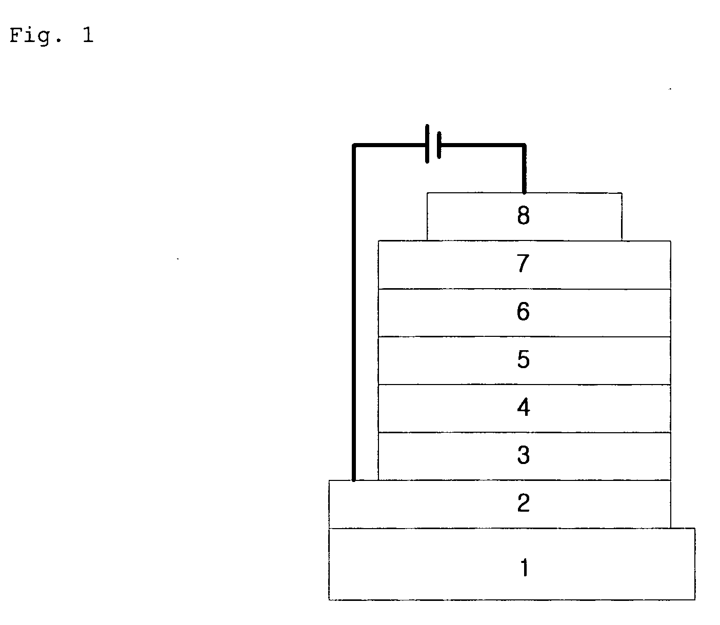
[0144]First, a transparent electrode ITO thin film (15Ω / □) (2) prepared from glass for OLED (produced by Samsung Corning) (1) was subjected to ultrasonic washing with trichloroethylene, acetone, ethanol and distilled water, sequentially, and stored in isopropanol before use.

[0145]Then, an ITO substrate was equipped in a substrate folder of a vacuum vapor-deposit device, and 4,4′,4″-tris(N,N-(2-naphthyl)-phenylamino)triphenylamine (2-TNATA) was placed in a cell of the vacuum vapor-deposit device, which was then ventilated up to 10−6 torr of vacuum in the chamber. Electric current was applied to the cell to evaporate 2-TNATA, thereby providing vapor-deposit of a hole injection layer (3) having 60 nm of thickness on the ITO substrate.

[0146]Then, to another cell of the vacuum vapor-deposit device, charged was N,N′-bis(α-naphthyl)-N,N′-diphenyl-4,4′-d...

Example

Example 2

Manufacture of an OLED (2)

[0149]An hole injection layer and a hole transport layer were formed according to the procedure of Example 1, and an electroluminescent layer was vapor-deposited as follows. In another cell of said vacuum vapor-deposit device, charged was H-5 as an electroluminescent host material, and an red phosphorescent compound (Compound 597) according to the present invention was charged to still another cell. The two materials were evaporated at different rates to carry out doping to vapor-deposit an electroluminescent layer (5) having 30 nm of thickness on the hole transport layer. The suitable doping concentration is 4 to 10 wt % on the basis of the host. Then, a hole blocking layer, an electron transport layer and an electron injection layer were vapor-deposited according to the same procedure as in Example 1, and then Al cathode was vapor-deposited in a thickness of 150 nm by using another vacuum vapor-deposit device to manufacture an OLED.


PUM


Abstract

The present invention relates to novel organic electroluminescent compounds exhibiting high luminous efficiency, and organic electroluminescent devices comprising the same. The organic electroluminescent compounds according to the invention are characterized in that they are represented by Chemical Formula (1):

Description

FIELD OF THE INVENTION[0001]The present invention relates to organic electroluminescent compounds and organic electroluminescent devices employing the compounds as an electroluminescent dopant. More specifically, the invention relates to novel iridium compounds which have red phosphorescent properties with high efficiency and can be employed as a material for forming an electroluminescent layer of an electroluminescent device, and organic electroluminescent devices using the same as an electroluminescent dopant.BACKGROUND OF THE INVENTION[0002]The most important factor to determine luminous efficiency in an OLED (organic light-emitting diode) is the type of electroluminescent material. Though fluorescent materials has been widely used as an electroluminescent material up to the present, development of phosphorescent materials is one of the best methods to improve the luminous efficiency theoretically up to four(4) times, in view of electroluminescent mechanism.[0003]Up to now, iridi...

Claims


Application Information

Patent Timeline
IPC IPC(8): H01J1/63C07F15/00
CPCC07F15/0033Y02E10/549Y02P70/50H10K85/633H10K85/331H10K85/342H10K50/11H10K2101/10H10K85/615H10K85/631
Inventor SHIN, HYO NIMEUM, SUNG JINCHO, YOUNG JUNKWON, HYUCK JOOKIM, BONG OKKIM, SUNG MINYOON, SEUNG SOO
Owner GRACEL DISPLAY INC
Why Eureka
Try Eureka