
Energy-Efficient Optoelectronic Smart Window

Active Publication Date: 2009-12-03
THE BOARD OF TRUSTEES OF THE UNIV OF ILLINOIS
View PDF15 Cites 136 Cited by
  • Summary
  • Abstract
  • Description
  • Claims
  • Application Information

AI Technical Summary

Benefits of technology

[0016]The window technologies of the prior art that control transmittance through the windows suffer from one or more of the following limitations: inability to efficiently reject or accept solar heat as desired, blocking daylight when only heat-blocking is desired, very expensive, difficult to implement on large enclosures, and incapable of being optimized for different climactic conditions. An optoelectronic or smart window of embodiments of the present invention overcomes these limitations, leading to highly cost-effective, programmable window systems with greatly improved energy efficiency and recycling capability. Specific advantages of the windows of embodiments of the present invention include, but are not limited to:
[0017](i) In controlling transmittance of the solar luminous flux into buildings, a window may efficiently separate the solar IR radiation from the visible radiation, allowing the IR radiation to be rejected by total internal reflection, without rejecting the visible daylight. The rejection of IR radiation reduces building air-conditioning costs; in addition, the transmission of visible radiation reduces energy costs for interior lighting.
[0018](ii) In winter months, a window of an embodiment of the present invention can be easily switched to accept the solar IR flux, enabling savings in building heating costs.

Problems solved by technology

The window technologies of the prior art that control transmittance through the windows suffer from one or more of the following limitations: inability to efficiently reject or accept solar heat as desired, blocking daylight when only heat-blocking is desired, very expensive, difficult to implement on large enclosures, and incapable of being optimized for different climactic conditions.

Method used


Image

  • Energy-Efficient Optoelectronic Smart Window
  • Energy-Efficient Optoelectronic Smart Window
  • Energy-Efficient Optoelectronic Smart Window

Examples


example 1

Fabrication Methods

[0074]Listed below are several methods which are utilized for fabrication of a film with a wide range of thicknesses and narrow uniformities to tolerance limits which are useful with the windows and methods described herein. For example, useful methods for forming a TIR layer include, but are not limited to:

[0075]Spin coating: Spin coating is a method of obtaining a uniform film thickness by disposing the coating solution with a viscosity on the substrate spinning at a specific rate usually ranging from 1000 rpm to 5000 rpm. It has been used to obtain relatively thin films.

[0076]Roll coating: This method uses 2 or 3 rolls, which rotate at a fast rate. First, a material feeding system coats the slurry material onto the first rotating roller; next, the slurry on the first roll is transferred to the second rotating roll. During this procedure, the desired uniformity and film thickness may be achieved. Finally, material on the second rotating roll is coated onto a fle...

example 2

Total Internal Reflection Layer Material Selection

[0085]The primary condition for total internal reflection is the selection of at least two materials with different refractive indices. In addition, the TIR material should have the following properties:

[0086]All materials used in the TIR layer should have a high optical transmittance in the visible spectrum (0.3˜0.7 μm) and the infrared spectrum (0.7˜3.0 μm).

[0087]All materials should be easy to coat and should not damage the underlying layers during processing. If the solvent used in the top layer to prepare the coating solution is similar to the one in the bottom layer, severe damage can be expected in the bottom layer during coating and drying.

[0088]Sharply defined 3-dimensional cells can be patterned with well known patterning processes. The widely accepted patterning methods include photolithography and etching, laser ablation, pattern printing, and micro-molding.

[0089]The materials should have a reliable resistance against hea...

example 3

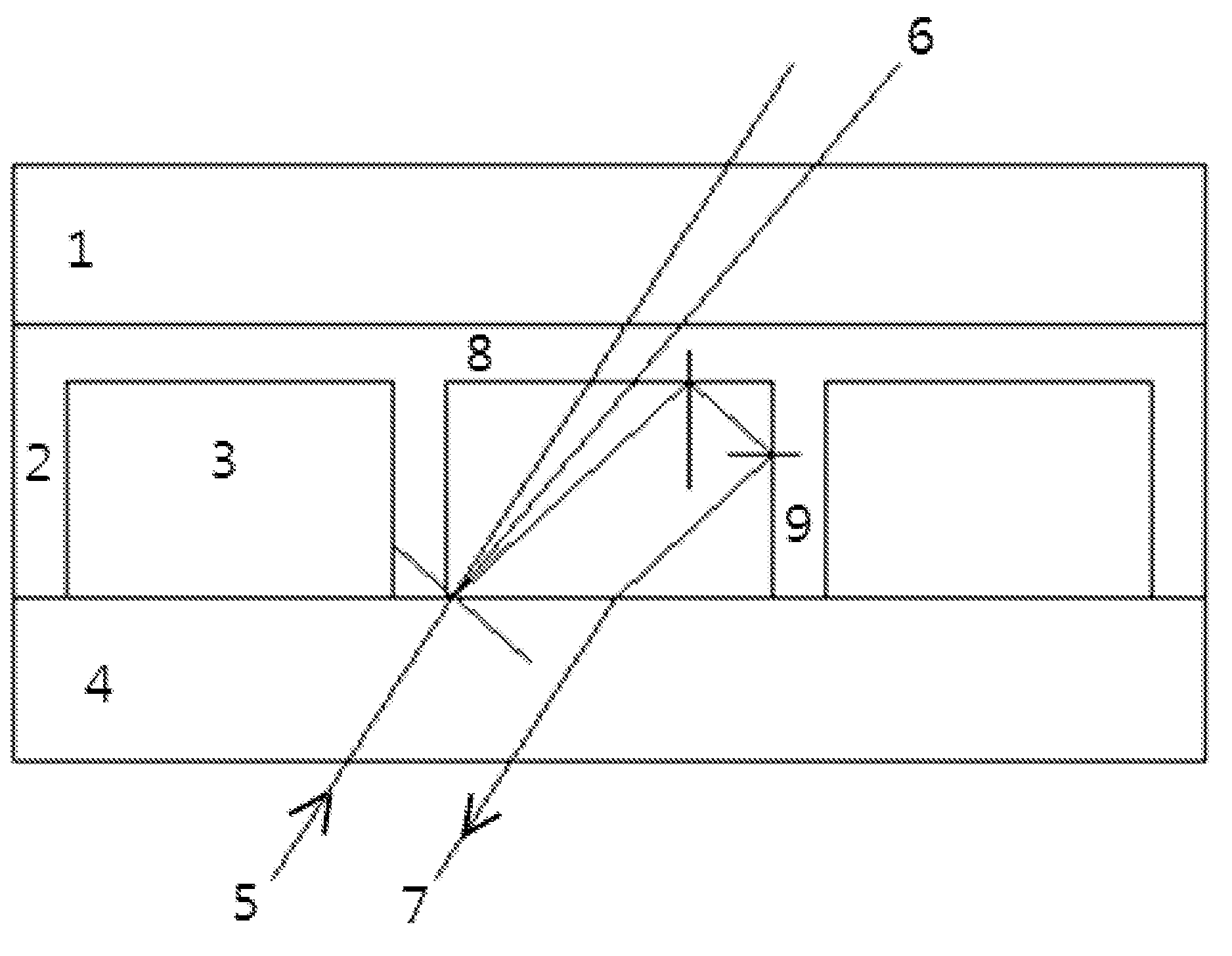
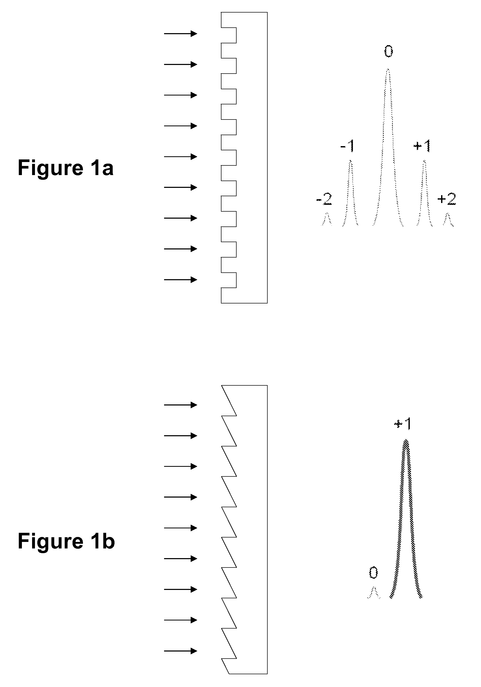
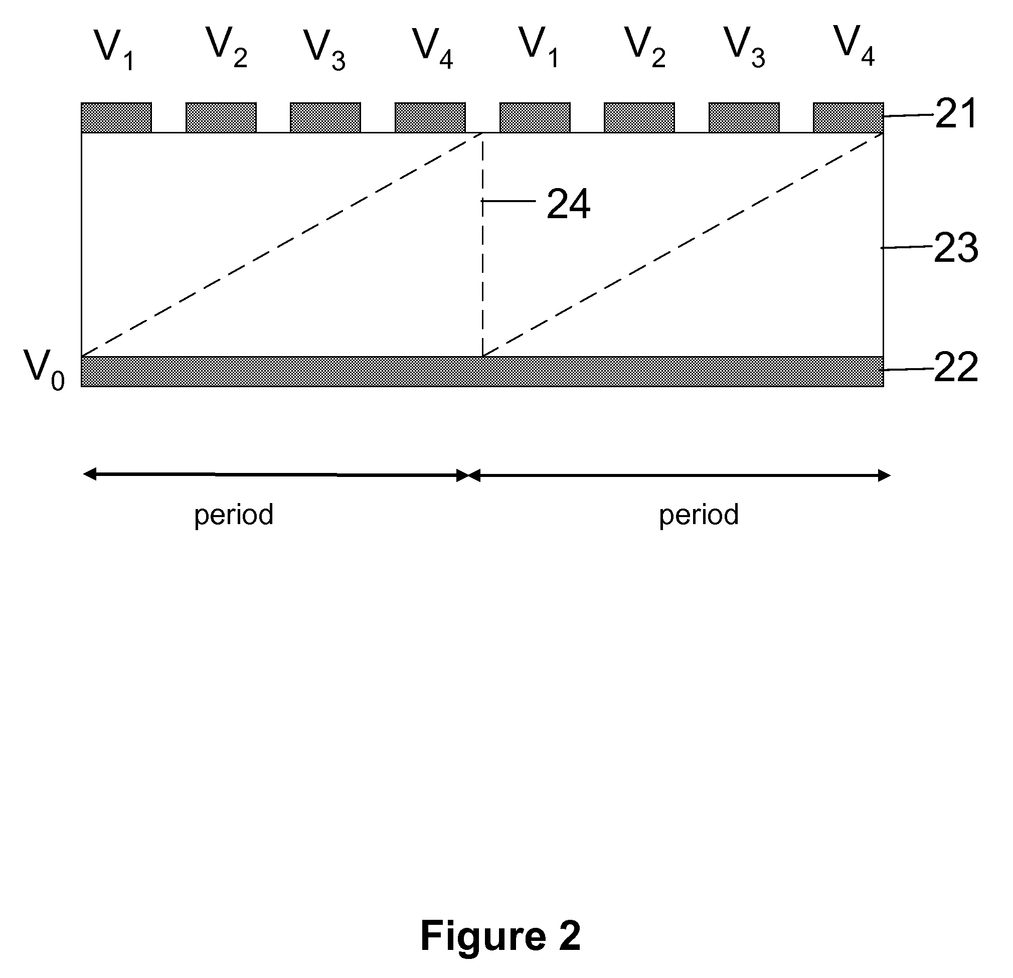
[0092]In an energy-efficient optoelectronic window system embodiment, several technical elements are utilized in novel ways. As already mentioned, one component of a window system is a transmissive blazed diffraction grating and a total internal reflection layer, which are attached, fabricated and configured in such a manner that their spectral characteristics can be selected in desirable ways to dynamically change their reflectivity and transmission for near-IR as well as visible light. The window structure, as illustrated in FIGS. 11a and 11b, comprises an outer glass pane, a programmable blazed diffraction grating layer, an inner glass pane, and a total internal reflection (TIR) pane. The programmable blazed diffraction grating layer is pixelated and its refractive index is pixel-wise modulatable by an array of electrodes, enabling a phase grating that can be programmed to function as a blazed grating only for the near-IR spectral component of the solar radiation. The programmabl...


PUM

PropertyMeasurementUnit
Lengthaaaaaaaaaa
Lengthaaaaaaaaaa
Thicknessaaaaaaaaaa

Abstract

In an aspect, described herein is a dynamically controllable optoelectronic smart window which utilizes a diffraction grating for selective transmission or rejection of a specific region of the electromagnetic spectrum, for example the infrared, near-infrared and / or visible regions. Window embodiments described herein may further utilize a selectively controlled and / or patterned total internal reflection layer to assist with the selective rejection of a specific spectral region while allowing for transmission of another specific spectral region. In another aspect, the present invention provides methods for dynamically controlling the transmission or rejection of solar near-infrared and / or visible radiation.

Description

CROSS REFERENCE TO RELATED APPLICATION[0001]This application claims priority under 35 U.S.C. 119(e) to U.S. Provisional Patent Application No. 61 / 057,617 filed on May 30, 2008, which is hereby incorporated by reference in its entirety to the extent not inconsistent with the disclosure herein.STATEMENT REGARDING FEDERALLY SPONSORED RESEARCH OR DEVELOPMENT[0002]Not Applicable.BACKGROUND OF THE INVENTION[0003]This invention is generally related to maximizing window efficiency and enabling control of the transmission of solar radiation into the interior of a building. This invention more specifically relates to advanced smart windows for high energy efficiency and recycling capability which include a diffraction grating for separation of different spectral regions for selective rejection and / or transmission of infrared, visible and ultraviolet radiation into the interior of a building. This invention also relates to a smart window having a selectively patterned micro cell array that aid...

Claims


Application Information

Patent Timeline
IPC IPC(8): G02F1/21G02B27/44G02F1/1333
CPCE06B9/24E06B2009/2464G02B5/1871G02F1/13306G02F2203/11G02F2201/086G02F2201/305G02F2202/40G02F1/1334
Inventor JAIN, KANTIJANG, LINUSHAN, YOON SOO
Owner THE BOARD OF TRUSTEES OF THE UNIV OF ILLINOIS
Learn More