
Effluent treatment process

a technology of effluent treatment and treatment process, which is applied in the direction of water treatment parameter control, specific water treatment objectives, cation exchangers, etc., can solve the problems of high phosphate content of treated effluent, chemical oxygen demands, and connection to a centralised effluent, so as to reduce the overall cost of handling the effluent, reduce the risk to the environment, and remove phosphate. high

Inactive Publication Date: 2010-02-11
OBRIEN PHILIP PATRICK PETER +1
View PDF8 Cites 3 Cited by
  • Summary
  • Abstract
  • Description
  • Claims
  • Application Information

AI Technical Summary

Benefits of technology

[0008]Furthermore, existing methods do not allow for the recovery of the phosphate once it has been removed from the effluent. Phosphate can be used in a number of by-products, such as in fertiliser, to great effect, and the recovery of the phosphate removed from the effluent will allow for the incorporation of the phosphate into by-products which is efficient and financially advantageous.
[0037]The advantage of using the polymer-based beads having a sponge-like constitution is that a large amount of nano-particles of iron oxide may be coated on the large surface area available as a result of the sponge-like constitution. The nano-particles of iron oxide offer high capacity, high surface area and rapid kinetics properties. Thus, the polymer based beads impregnated with iron oxide nano-particles are seen as a particularly effective substance for removing the phosphate from the effluent, and furthermore, they allow for relatively simple backwashing and achieve good longevity in service.

Problems solved by technology

A significant challenge facing local authorities is to ensure that adequate effluent treatment facilities are provided for both new and existing housing developments in remote areas where connection to a centralised effluent treatment plant is either uneconomical or impractical and dedicated effluent treatment facilities for the housing development are provided.
A particular problem with known processes is that treated effluents still typically contain high levels of phosphate, suspended solids, chemical oxygen demands (CODs) and biological oxygen demands (BODs) which are harmful to the environment.
Phosphate can be particularly harmful as high levels of phosphate in water systems leads to eutrophication of the water system which will encourage the growth and decomposition of oxygen-depleting plants such as algal bloom, and result in harm to other organisms including fish.
The biological removal method tends to be favoured as it has a lower overall operating cost, when compared with the chemical precipitation method, however, the biological removal method may not be as reliable and cannot achieve the same levels of phosphate removal as a well-run chemical precipitation method.
There are problems with both of these existing methods.
Both methods are largely unreliable when the level of phosphorus is required to be reduced below 1 mg / Litre.
The existing methods using the biological and chemical methods are incapable of adjusting to fluctuating levels of phosphate in the effluent as the methods are typically set up to introduce a predetermined amount of the biological or chemical substance into the effluent as the effluent flows through the treatment stage.
Furthermore, existing methods do not allow for the recovery of the phosphate once it has been removed from the effluent.
A further problem with the existing methods is that many of the methods produce large volumes of sludge which is expensive to dispose of in a secure and safe manner.
Such an arrangement has been found to lead to problems when varying amount of phosphates are present in the wastewater.
Due to the varying amounts of phosphate, the proposed solutions may not always be sufficient to reduce the phosphate levels to below 1 mg / Litre.
Such sorbent materials are not always ideal for reducing the phosphate levels to below 1 mg / Litre.

Method used


Image

  • Effluent treatment process
  • Effluent treatment process
  • Effluent treatment process

Examples


Embodiment Construction

[0061]The invention will now be more clearly understood from the following description of some embodiments thereof given by way of example only, in which:

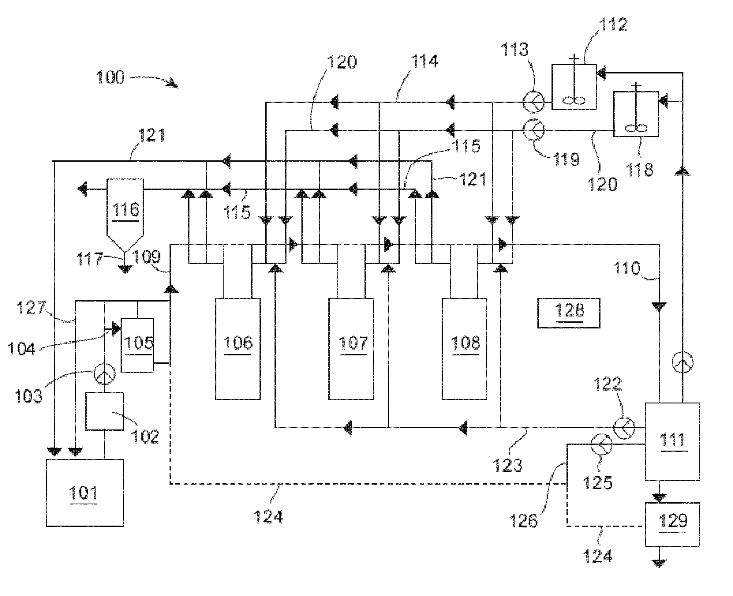
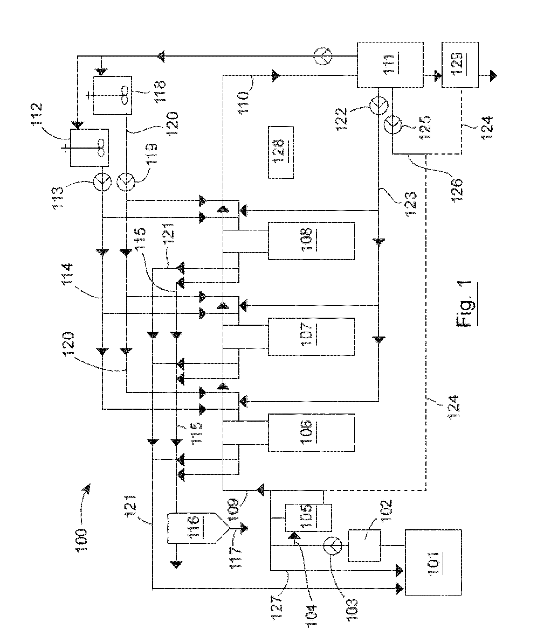
[0062]FIG. 1 is a diagrammatic representation of a first effluent treatment process assembly according to the present invention; and,

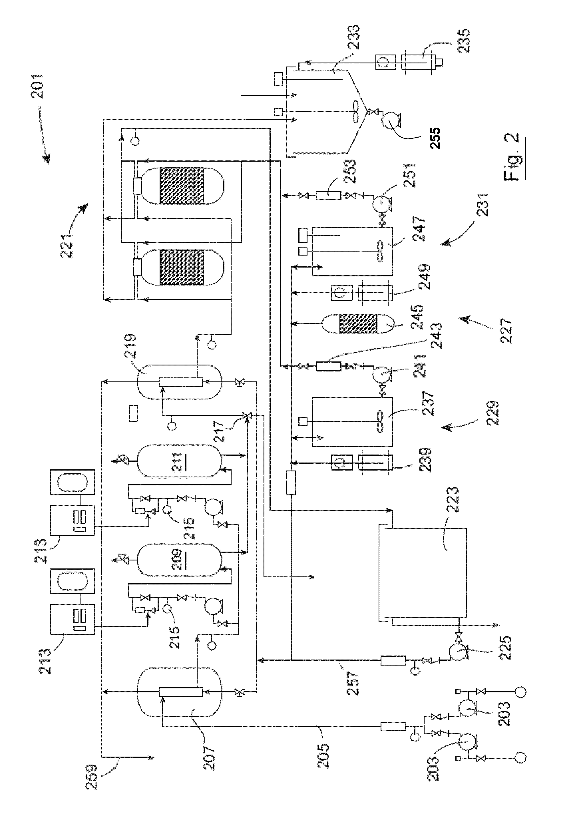
[0063]FIG. 2 is a diagrammatic representation of a second effluent treatment process according to the present invention.

[0064]Referring to FIG. 1, there is shown an effluent treatment assembly, indicated generally by the reference numeral 100, comprising a waste water treatment plant 101 from which partially treated sewage coming is collected in a sump 102. The partially treated sewage is delivered by a pump 103, at a pre-determined rate, through a conduit 104 to a primary filter 105. The effluent may be analysed, to determine flow rate, pH level, turbidity and phosphate content en route to the primary filter 105 or directly subsequent to the primary filter 105. If the effluent does not meet the requi...


PUM

PropertyMeasurementUnit
diameteraaaaaaaaaa
concentrationsaaaaaaaaaa
volumeaaaaaaaaaa

Abstract

According to the invention there is provided a tertiary effluent treatment process for reducing the phosphate levels in effluent. The process comprises the steps of delivering effluent from a wastewater treatment plant to a primary filter, delivering the filtered effluent to a series of two or more phosphate removal filters, delivering the filtered phosphate-depleted effluent to a treated water tank as treated water, delivering the filtered phosphate-depleted effluent from the treated water tank to a discharge tank as treated water; and, discharging the treated water from the discharge tank as required. Each phosphate removal filter comprises a plurality of polymer-based beads having nano-particles of iron oxide coated thereon. The advantage of using a series of two or more phosphate removal filters is that the process can deliver a final effluent containing specific pre-determined levels of phosphate that may be as low as 0.01 mg / L of effluent, but will in all cases be below 1 mg / L. The series of two or more filters also allow the process to accommodate variations in the phosphate content of the effluent without affecting the level of phosphate in the discharge, and, the system can be retro-fit to the end of any type of existing waste water treatment plant or can be integrated into a new facility.

Description

INTRODUCTION[0001]This invention relates to an effluent treatment process and an assembly for carrying out the effluent treatment process. More particularly, the present invention relates to an effluent treatment process and assembly for carrying out that process on final effluent that has already undergone prior treatment preferably in a biological effluent treatment plant. In particular, the invention is particularly designed to remove phosphorus from treated effluent to a level less than 0.02 mg / Litre.[0002]Throughout the following description, it should be understood that the term “phosphate” can refer to either a composition comprising phosphorus or to the chemical element phosphorus itself, and, that any reference to “phosphate” should be interpreted as such.[0003]A significant challenge facing local authorities is to ensure that adequate effluent treatment facilities are provided for both new and existing housing developments in remote areas where connection to a centralised ...

Claims


Application Information

Patent Timeline
Patent Type & Authority Applications(United States)
IPC IPC(8): C02F1/42
CPCC02F1/281C02F1/288C02F1/78C02F2303/16C02F2209/06C02F2209/11C02F2209/18C02F2101/105
Inventor O'BRIEN, PHILIP PATRICK PETERLEONARD, OWEN THOMAS
Owner OBRIEN PHILIP PATRICK PETER
Learn More