Agile-beam laser array transmitter

a laser array transmitter and beam beam technology, applied in multiplex communication, semiconductor lasers, instruments, etc., can solve the problems of limiting pointing accuracy, affecting the accuracy of pointing, so as to achieve the effect of fast steering

Active Publication Date: 2010-02-25
MASSACHUSETTS INST OF TECH
View PDF9 Cites 94 Cited by
  • Summary
  • Abstract
  • Description
  • Claims
  • Application Information

AI Technical Summary

Benefits of technology

[0018]Various embodiments may be used in applications including, but not limited to: free-space optical communications; optical scanning (e.g., retinal scanning or bar-code scanning); raster-scanning projectors; display projection; light detection and ranging (lidar); image capture; optical character recognition; scanning laser microscopy; non-destructive testing; printing; facsimiles; map making; web inspection; color print processing; phototypesetting and platemaking; laser marking; material processing; DNA analysis; and drug discovery. Compared to other beam steering technologies, example embodiments of the present invention offer faster steering over a wider field of view in a much smaller package.

Problems solved by technology

Galvanometers and piezoelectric scanners tend to be bulky and generally require high-current and high-voltage servo drivers, respectively.
Position drift dues to temperature fluctuations limits the pointing accuracy, as does hysteresis in the response to the servo driver.
Although Risley prisms can be mounted compactly along independent rotational axes, the prisms and mounts have extremely tight manufacturing tolerances.
For example, imprecisely matched prisms may not be able to steer beams along the optical axis.
In addition, chromatic aberrations inherent in dispersive optics cause wavelength-dependent deviations in the steering angle.
Like mechanical scanners, AODs tend to be bulky and can only steer beams in one dimension.
AODs also diffract multiple orders (even when Bragg-matched), introducing unwanted beams into the scene being illuminated.
Although MEMS devices are quite compact, their angular field-of-view in any one dimension tends to be no more than a few degrees at most.
MEMS device cannot operate at rates much faster than a few kilohertz.
In addition, surface effects, such as stiction (i.e., static friction), can cause MEMS components to stick in certain positions during fabrication and operation, effectively ruining the devices.
Beam steering with liquid-crystal spatial light modulators (SLMs) also tends to suffer from limited field-of-view and slow (kilohertz) steering speeds.
Because the SLM uses polarization effects to imprint spatial phase modulation on the incident beam, only a fraction of the incident beam is transmitted (or reflected), dramatically reducing the optical transmission efficiency of the system.
As a result, its scanning speed will be limited to kilohertz rates, at best.
At optical frequencies, however, coherent control is quite difficult because the wavelength is so short (usually about 1 μm).
Cohering multiple independent sources, even using injection-locking techniques, usually does not provide long-term phase stability needed for most beam steering applications.
Unfortunately, environmental perturbations, such as thermal and mechanical drift, make it impractical to match paths to within these lengths.

Method used


Image

  • Agile-beam laser array transmitter
  • Agile-beam laser array transmitter
  • Agile-beam laser array transmitter

Examples


Embodiment Construction

[0034]A description of example embodiments of the invention follows.

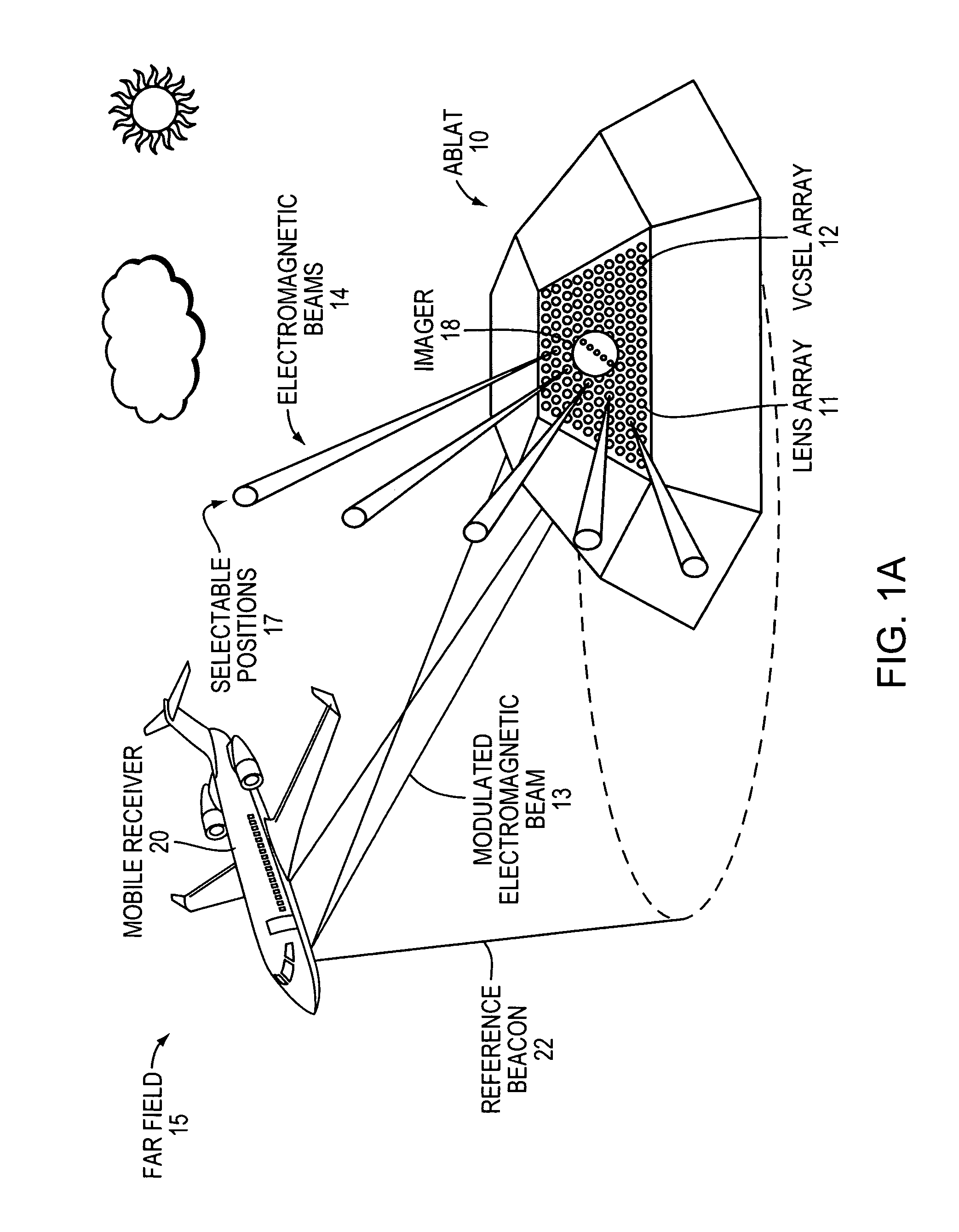
[0035]FIG. 1A is a system-level diagram that illustrates free-space optical communications between an Agile-Beam Laser Array Transmitter (ABLAT) 10 and mobile receiver 20, such as an unmanned aerial vehicle, airplane, helicopter, car, truck, or other vehicle. The mobile receiver 20 shown in FIG. 1A uses a beacon generator (not shown) to project a reference beacon 22 towards an imager 18 mounted with the ABLAT 10. A control circuit determines the angle-of-arrival of the reference beacon 22 using the signal detected by the imager 18, then causes the ABLAT 10 to project a modulated electromagnetic beam 13 towards the mobile receiver 20, completing the communications link between the ABLAT 10 and the mobile receiver 20. The reference beacon can also be modulated to permit two-way communication between the mobile receiver 20 and the ABLAT 10.

[0036]The ABLAT 10 shown in FIG. 1A is mounted on a faceted surface and includes...


PUM


Abstract

An Agile-Beam Laser Array Transmitter (ABLAT) uses an array of emitters and an array of lenses to project electromagnetic beams over a wide angular coverage area in the far field. Differences in the separation pitches of the two arrays allows the ABLAT to project beams to contiguous and/or overlapping positions, depending on the ratio of the separation pitches and the lens focal length. Compared to other beam steering technology, the ABLAT is a smaller, lighter, and more efficient means of projecting beams over wider angular coverage areas. Various embodiments can be used in any beam steering application, including, but not limited to: free-space optical communications; light detection and ranging (lidar); optical scanning (e.g., retinal or bar-code scanning); display projection; image capture; optical character recognition; scanning laser microscopy; non-destructive testing; printing; facsimiles; map making; web inspection; color print processing; phototypesetting and platemaking; laser marking; material processing; DNA analysis; and drug discovery.

Description

RELATED APPLICATION[0001]This application claims the benefit of U.S. Provisional Application No. 61 / 126,252, filed on May 2, 2008. The entire teachings of the above application are incorporated herein by reference.GOVERNMENT SUPPORT[0002]The invention was supported, in whole or in part, by government funding under Contract No. F19628-00-C-0002 from the United States Air Force comprising Lincoln Laboratory research programs 1-98123, 2219-6, 1312, and 1598. The Government has certain rights in the invention.BACKGROUND OF THE INVENTION[0003]Free-space optical communications, light detection and ranging (lidar), and optical scanning all require some means of steering optical beams. Usually, fast steering and large scan angles are the two most important considerations for these applications. In some cases, the beams are hopped rather than steered from location to location, a feature sometimes known as agile beam steering.[0004]Perhaps the most common way to steer optical beams is by refl...

Claims


Application Information

Patent Timeline
Patent Type & Authority Applications(United States)
IPC IPC(8): H04B10/00G02B27/12
CPCH01S5/005H01S5/423H01S5/4087H01S5/4031G01S7/4815
Inventor SHAW, GARY A.CANDELL, LAWRENCE M.
Owner MASSACHUSETTS INST OF TECH
Why Eureka
Try Eureka