Induction heated, hot wire welding

a technology of induction heating and hot wire welding, which is applied in the direction of welding apparatus, laser beam welding apparatus, manufacturing tools, etc., can solve the problems of increasing the risk of electrical shorts, the current hot wire technique has limitations, and the process of iwamoto offers no practical means to prevent electrical contact between the induction coil and the filler wire, so as to prevent heat loss and high temperature corrosion (galling), the effect of high thermal shock resistan

Inactive Publication Date: 2010-03-11
BABCOCK & WILCOX TECHNICALSERVICES GRP INC
View PDF6 Cites 54 Cited by
  • Summary
  • Abstract
  • Description
  • Claims
  • Application Information

AI Technical Summary

Benefits of technology

[0009]The present invention addresses the limitations in the known art and is drawn to an improvement of the hot wire welding process. This inherent problem (mentioned in the above paragraph) solved by the proposed invention is the use of a ceramic guide tube inside of the induction coil and wire delivery guide. Here, an induction coil is used to preheat the filler metal prior to its entering the welding puddle/arc region. An induction coil is placed in close proximity to the welding arc. The filler wire is guided by a ceramic insulator so that the filler wire passes through the center of

Problems solved by technology

The current hot wire technique has some limitations.
The proposed process by Iwamoto offers no practical means to prevent electrical contact between the induction coil and filler wire as well as a means to support/guide the heated filler metal to the desired delivery point, being the welding arc.
As the wire is heated there is the tendency for the wire to sag, thereby increasing the risk of an electrical short.
The heating of the wire reduces the axial compression strength of the wire, where there is a tendency to buckle if not fully supported to the delivery point of t

Method used


Image

  • Induction heated, hot wire welding
  • Induction heated, hot wire welding
  • Induction heated, hot wire welding

Examples


Embodiment Construction

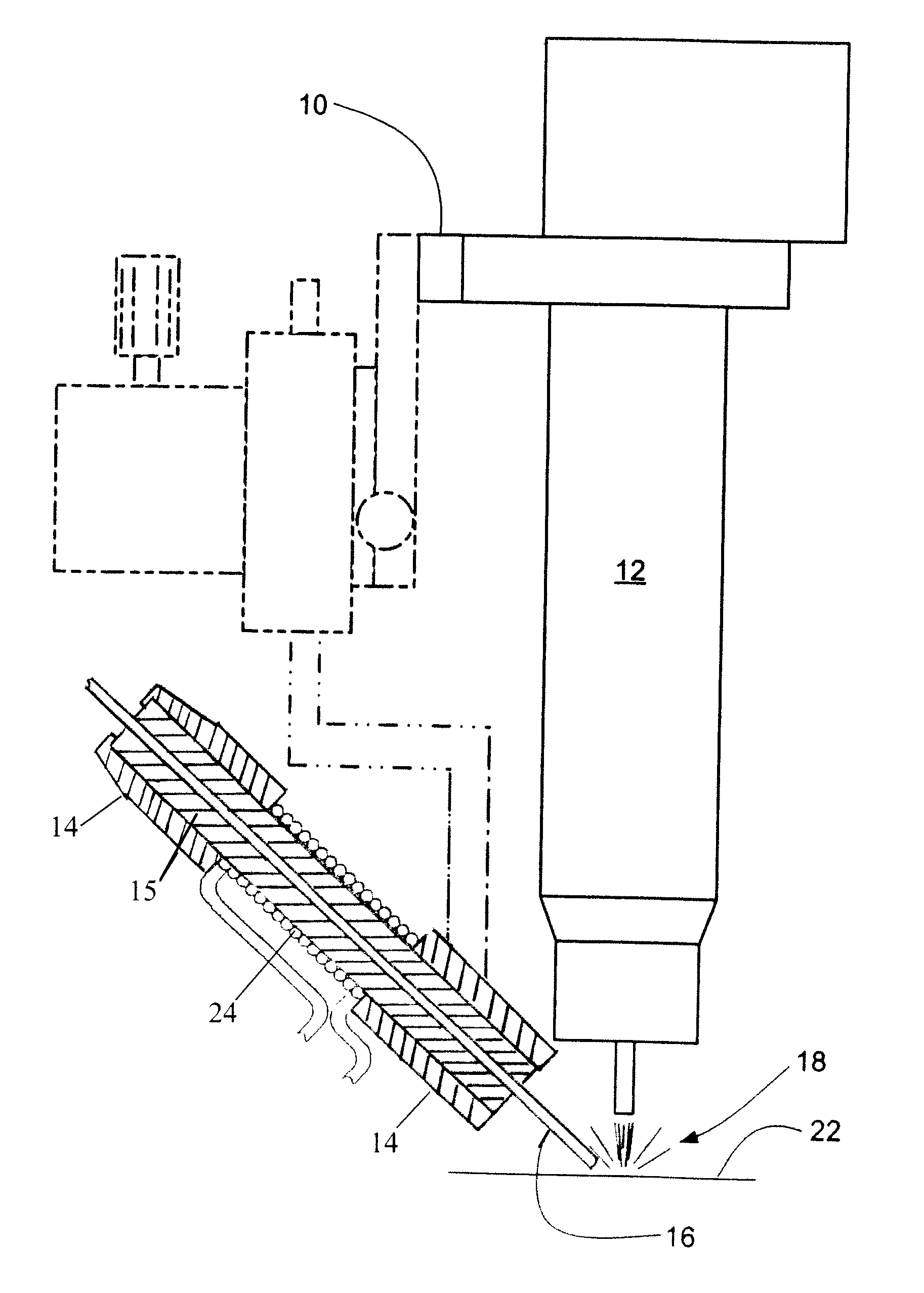
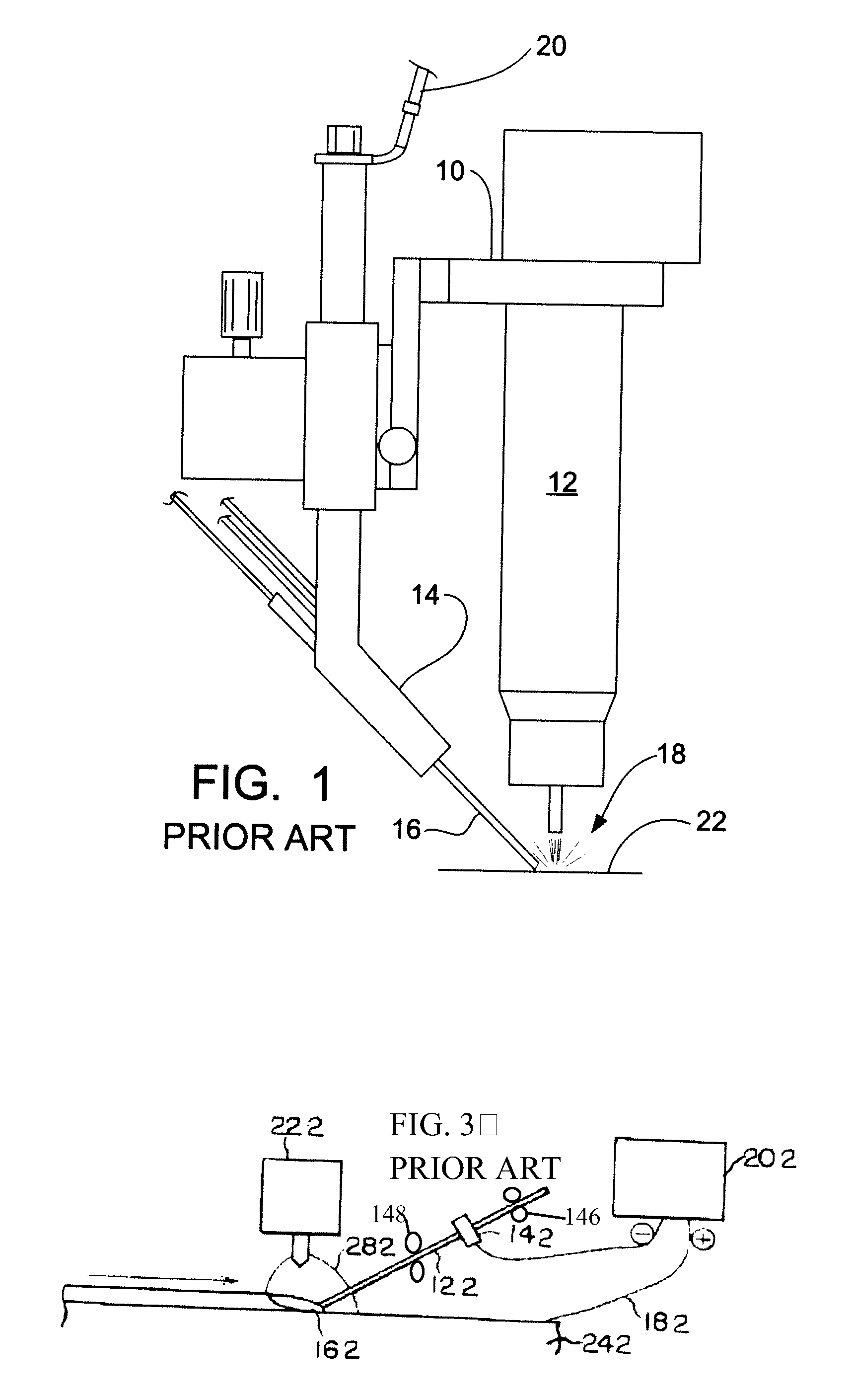
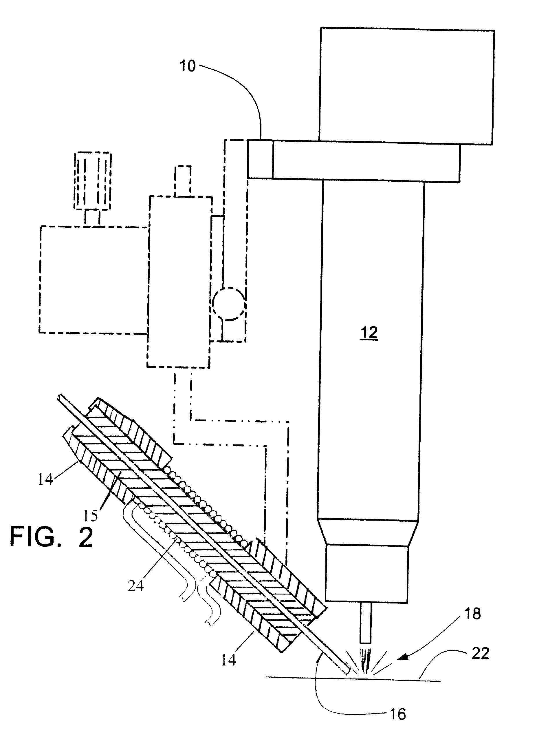
[0015]The prior art arrangement for HW-GTAW (hot wire gas tungsten arc welding) is illustrated in FIGS. 1 and 3. For FIG. 1, a framework 10 supports the gas tungsten arc torch 12, and a delivery guide 14 for the filler metal wire 16. The delivery guide 14 is used to guide the filler metal wire 16 to the area of the welding arc 18 adjacent the gas tungsten arc torch 12. Means for delivering electrical current to the filler metal wire 16 is supported on the framework. An electrical cable 20 is provided with an electrical contact that is in contact with the filler metal wire 16 in the delivery guide 14 in close proximity to the welding arc 18 to deliver a current into the filler wire 16. The electrical current preheats the wire 16 before it reaches the welding arc 18 as long as the filler wire 16 maintains a closed electrical circuit by remaining in contact with the weld puddle on the work piece 22.

[0016]For FIG. 3, a solenoid coil is used to inductively heat a traveling filler wire fo...


PUM

PropertyMeasurementUnit
Temperatureaaaaaaaaaa
Flow rateaaaaaaaaaa
Currentaaaaaaaaaa

Abstract

A hot wire welding process. An induction coil is used to preheat the filler metal wire prior to its entering the welding puddle/arc region. An induction coil is placed in close proximity to the welding arc. The filler wire is guided and supported by a delivery guide so that the filler wire passes through the center of, and is insulated from, the induction coil. The induction coil induces a current flow in the filler wire. The current produces heat as a result of the electrical resistivity of the filler wire. The heat produced raises the temperature of the filler wire just before it is fed into the weld arc region, thus reducing the energy required from the welding arc to melt the filler metal wire into the weld puddle.

Description

RELATED APPLICATION DATA[0001]This application is a continuation-in-part of application Ser. No. 11 / 755,795 filed on May 31, 2007.FIELD AND BACKGROUND OF INVENTION[0002]The hot wire process has been used almost exclusively with gas tungsten arc welding. The hot wire gas tungsten arc welding (GTAW) process is an arc welding process that uses an electric arc between a non-consumable tungsten / tungsten alloy electrode and the work piece to create a molten weld pool. The region immediately around the electrode is protected by the flow of a shielding gas that protects the electrode tip, weld pool, and solidifying weld metal from atmospheric contamination. The arc is produced by passing electrical current from the electrode to the work piece through the conductive ionized shielding gas column. Heat generated from the welding arc is used to melt the base material to form a weld puddle. The electrode can be progressively moved along the surface of the work piece to produce a weld pass. A con...

Claims


Application Information

Patent Timeline
IPC IPC(8): B23K9/00
CPCB23K9/1093B23K9/133B23K26/203B23K9/173B23K26/147B23K9/167B23K26/211
Inventor MCANINCH, MICHAEL D.
Owner BABCOCK & WILCOX TECHNICALSERVICES GRP INC
Why Eureka
Try Eureka