Separation membrane complex, and method for manufacturing the separation membrane complex

Active Publication Date: 2010-03-25
NGK INSULATORS LTD
View PDF6 Cites 7 Cited by
  • Summary
  • Abstract
  • Description
  • Claims
  • Application Information

AI Technical Summary

Benefits of technology

[0033]The first separation membrane complex according to the present invention has an intermediate layer having a thickness of 10 to 100 μm, which is thin. Therefore, a separation membrane complex according to the present invention has small total pressure loss and can obtain high flux.
[0034]The second separation membrane complex according to the present invention can suppress pressure loss because the intermediate layer is constituted of an aggregate. As a result, since permeability of permeable gas improves, the second separation membrane complex according to the present invention has high separation coefficient and high fl

Problems solved by technology

However, when a filter was actually manufactured by forming a carbon membrane on a surface of a (ceramic) porous body, it was not

Method used


Image

  • Separation membrane complex, and method for manufacturing the separation membrane complex
  • Separation membrane complex, and method for manufacturing the separation membrane complex
  • Separation membrane complex, and method for manufacturing the separation membrane complex

Examples


example 1

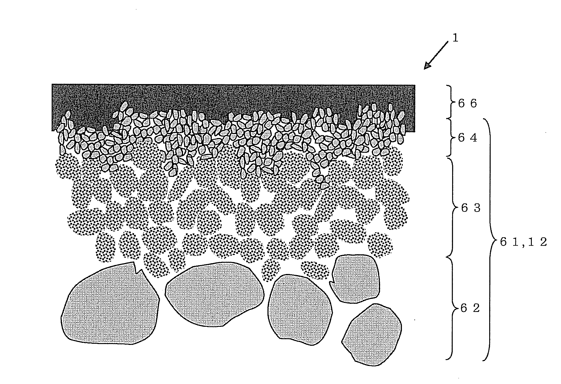
[0068]A monolith-shaped substrate having an average particle diameter of 10 to 100 μm and an average pore diameter of 1 to 30 μm was manufactured by means of forming by extrusion forming and firing. Next, the alumina particles (secondary particles) which is constituted of an aggregate having a primary particle diameter of 0.01 to 1 μm and which has an average particle diameter of 0.3 to 10 μm were deposited on the internal wall faces of the cells in the substrate obtained above by a filtration membrane-forming method with adjusting the membrane thickness by the membrane formation time, followed by firing to form an intermediate layer having a thickness of 10 μm and the average pore diameter of 0.1 to 3 μm. Then, on the intermediate layer, alumina particles having an average particle diameter of 0.03 to 1 μm were deposited by a filtration membrane-forming method with adjusting the membrane thickness by the membrane formation time, followed by firing to form a surface layer having a t...

example 2

[0071]A separation membrane complex was manufactured in the same manner as in Example 1 except that the thickness of the intermediate layer was made to be 100 μm and evaluated by the water-ethanol pervaporation separation method under the same conditions as in the Example 1. Table 1 shows the particle form (aggregate or dense body) of the intermediate layer, thickness of the intermediate layer, the pervaporation separation performance (separation coefficient, flux), and pressure loss. In addition, FIG. 4 shows a photograph of a cross section of the porous body after the carbon membrane was formed. In Example 2, two porous bodies were manufactured under the same conditions, and FIG. 4 is a photograph of a cross section of one of the porous bodies.

example 3

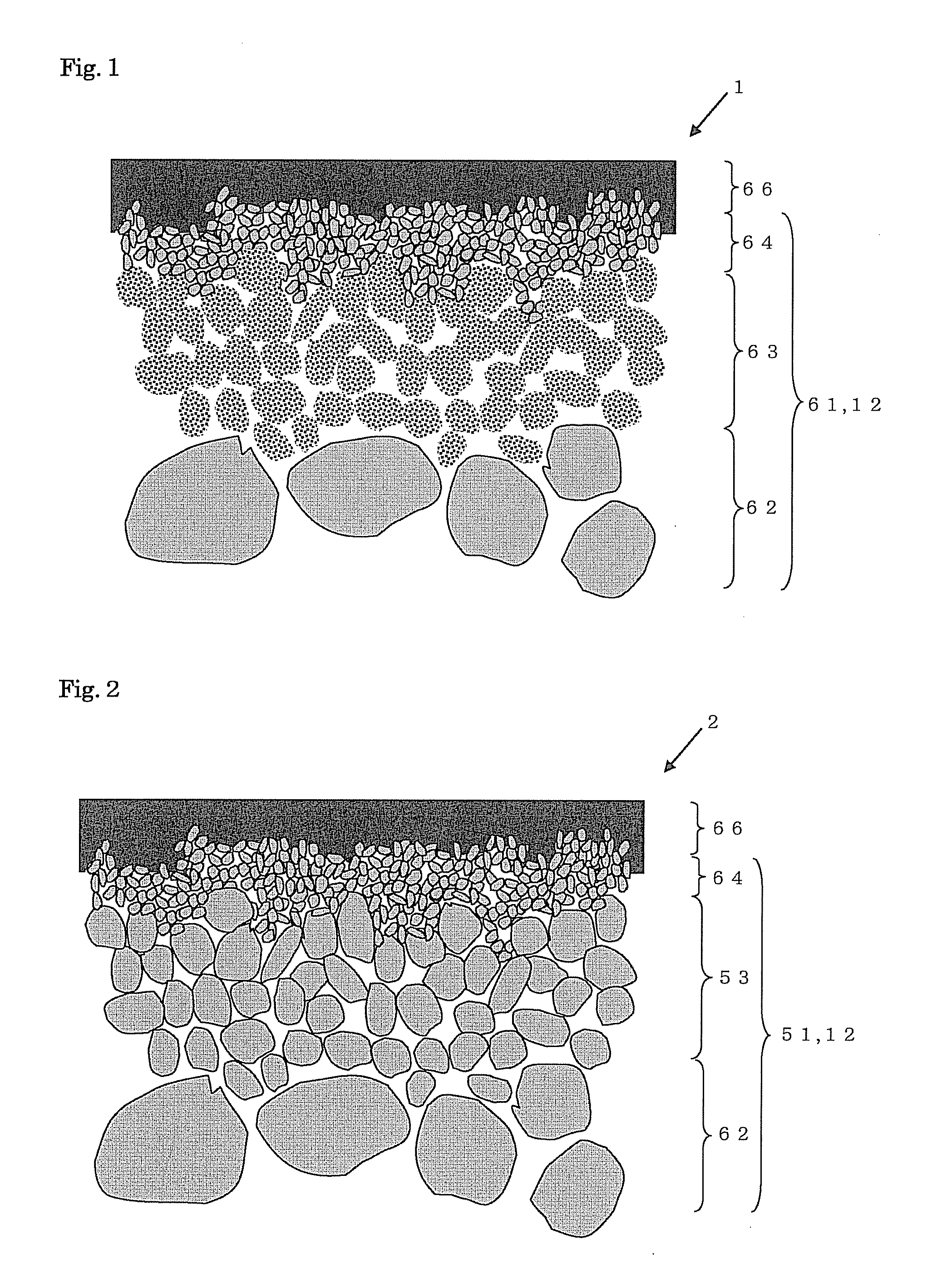
[0072]A separation membrane complex was manufactured in the same manner as in Example 1 except that alumina particles constituted of a dense body were used upon forming the intermediate layer and that the thickness of the intermediate layer was made to be 50 μm and evaluated by the water-ethanol pervaporation separation method under the same conditions as in the Example 1. Table 1 shows the particle form (aggregate or dense body) of the intermediate layer, thickness of the intermediate layer, the pervaporation separation performance (separation coefficient, flux), and pressure loss.


PUM

PropertyMeasurementUnit
Thicknessaaaaaaaaaa
Volumeaaaaaaaaaa
Volumeaaaaaaaaaa

Abstract

A separation membrane complex 1 where a carbon membrane 66 is formed directly on a porous body 61 (surface layer 64) and an intermediate layer 63 has a thickness of 10 to 100 μm can be used as a filter having improved flux and selectivity in comparison with a conventional one.

Description

TECHNICAL FIELD[0001]The present invention relates to a separation membrane complex which is a complex having a porous body and a separation membrane formed on a surface of the porous body and a method for manufacturing the separation membrane complex.BACKGROUND ART[0002]There is a technical desire to selectively separate a specific substance (gas or the like) from a mixture of a plurality of substances (gas or the like) at a molecular level, and, as a filter responding to the desire, there are generally known ones each employing polysulfone, silicon, polyamide, polyimide, or the like as a separation membrane.[0003]However, since these have separation membrane made of polymer resin, these inherently have a problem that target substance for separation is limited because the membrane is easily altered and deteriorated when an organic solvent is contained in the mixture serving as the target substance for separation.[0004]Therefore, in recent years, as a filter excellent in chemical st...

Claims


Application Information

Patent Timeline
IPC IPC(8): B01D71/02B01D67/00B05D5/00
CPCB01D63/066B01D67/0046B01D67/0067B01D69/02B01D2325/04B01D71/021B01D71/025B01D71/027B01D71/028B01D69/12
Inventor ICHIKAWA, AKIMASANONAKA, HISAYOSHITOMITA, TOSHIHIRO
Owner NGK INSULATORS LTD
Why Eureka
Try Eureka