Microwave plasma containment shield shaping

Inactive Publication Date: 2010-04-01
APPLIED MATERIALS INC
View PDF71 Cites 31 Cited by
  • Summary
  • Abstract
  • Description
  • Claims
  • Application Information

AI Technical Summary

Benefits of technology

[0005]Embodiments of the present invention provide microwave systems and methods for achieving better control of process and film properties by optimizing plasma containment shield shaping around an antenna. By using a containment shield, plasma generated by microwaves may become more homogeneous, and the pressure inside a processing chamber may be reduced. By optimizing the containment shield shaping, the lifetime of metastable radical species may be increased. One aspect of extending the lifetime of metastable radical species is to allow better

Problems solved by technology

However, this technique does not provide a homogeneous assist to enhance plasma generation.
It also does not provide enough plasma density to sustain its own discharge without the

Method used


Image

  • Microwave plasma containment shield shaping
  • Microwave plasma containment shield shaping
  • Microwave plasma containment shield shaping

Examples


Embodiment Construction

1. Overview of Microwave-Assisted Deposition

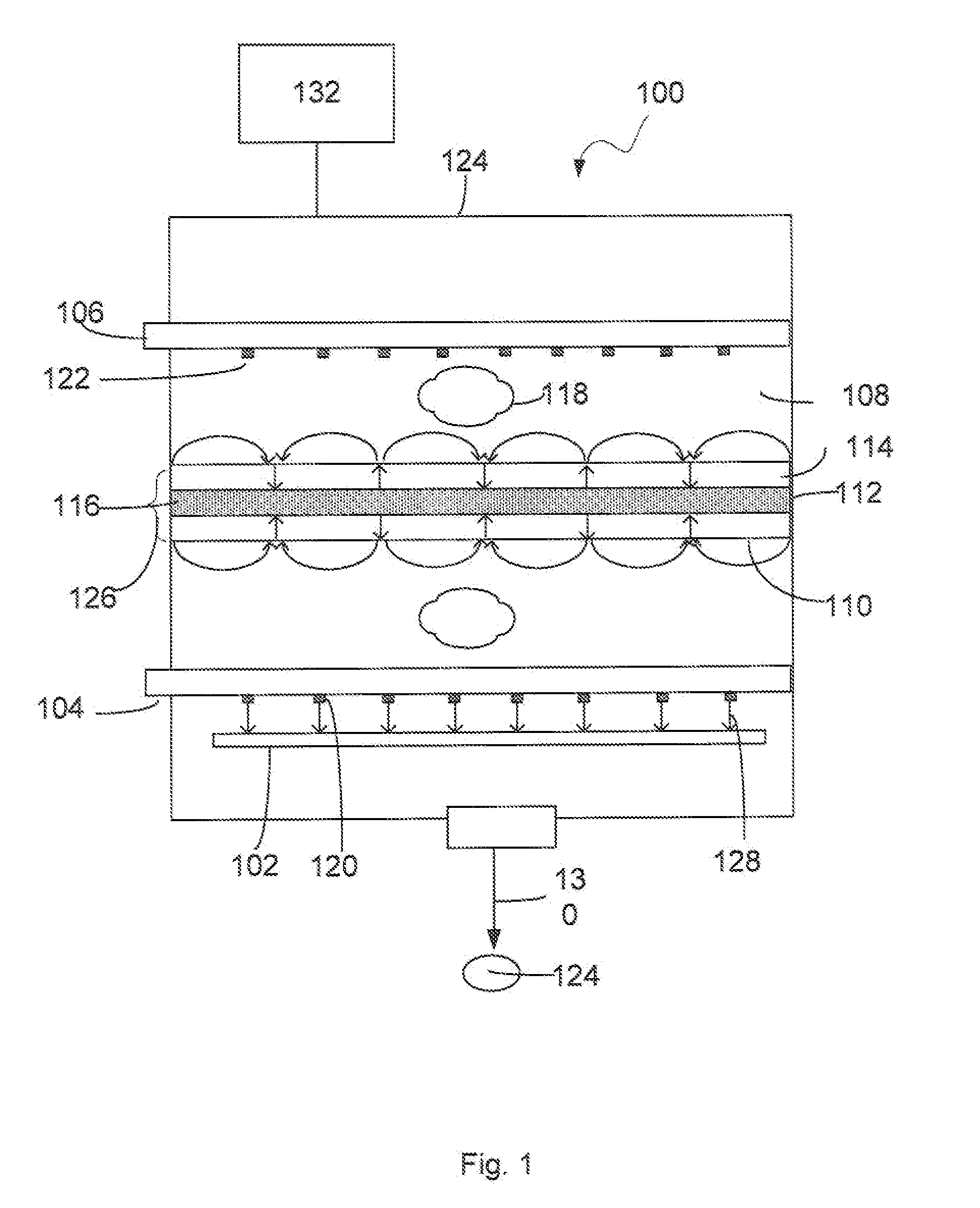
[0026]Microwave plasma has been developed to achieve higher plasma densities (e.g. ˜1012 ions / cm3) and higher deposition rates, as a result of improved power coupling and absorption at 2.45 GHz when compared to a typical radio frequency (RF) coupled plasma sources at 13.56 MHz. One drawback of using RF plasma is that a large portion of the input power is dropped across the plasma sheath (dark space). By using microwave plasma, a narrow plasma sheath is formed and more power can be absorbed by the plasma for creation of radical and ion species, which increases the plasma density and obtains a narrow energy distribution by reducing collision broadening of the ion energy distribution.

[0027]Microwave plasma also has other advantages, such as lower ion energies with a narrow energy distribution. For instance, microwave plasma may have low ion energy of 0.1-25 eV, which leads to lower damage when compared to processes that uses RF plasma. In con...


PUM

PropertyMeasurementUnit
Dielectric polarization enthalpyaaaaaaaaaa
Pressureaaaaaaaaaa
Shapeaaaaaaaaaa

Abstract

The present invention provides microwave systems and methods for achieving better control of process and film properties by optimizing plasma containment shield shaping around an antenna. By using a containment shield, plasma generated by microwave may become more homogeneous, and the pressure inside a processing chamber may be reduced. By optimizing the shape of the containment shield, the lifetime of metastable radical species may be increased. One aspect of extending the lifetime of metastable radical species is to allow better control of chemical reaction and thus help achieve the desired film properties. For an array of antennas, the containment shield comprises a dielectric coated metal base with dividers between the antennas. The divider comprises a dielectric material or a mixture of a dielectric layer and a dielectric coated metal layer, and allows coupling among the antennas. Such a dielectric coated metal containment shield may be easier to be manufactured at lower cost than a containment shield comprising only dielectric material such as quartz.

Description

BACKGROUND OF THE INVENTION[0001]For thin film deposition, it is often desirable to have a high deposition rate to form coatings on large substrates, and flexibility to control film properties. Higher deposition rate may be achieved by increasing plasma density or lowering the chamber pressure. For plasma etching, higher etching rate may sometimes be helpful for shortening processing cycle time. A high plasma density source is often desirable.[0002]In chemical vapor deposition (CVD), a film is formed by chemical reaction near the surface of a substrate. Typically, reactive gases are introduced into a processing chamber. The reactive gases may decompose from heat to form plasma. Then, chemical reaction may occur on the surface of a substrate to form a film over the substrate. Volatile byproducts may be produced and transported away from the processing chamber. Examples of common CVD technologies include thermal CVD, low pressure CVD (LPCVD), plasma-enhanced CVD (PECVD), microwave pla...

Claims


Application Information

Patent Timeline
IPC IPC(8): C23C14/34
CPCC23C16/511C23C16/515H01J37/32477H01J37/32357H01J37/32422H01J37/32192
Inventor STOWELL, MICHAEL W.
Owner APPLIED MATERIALS INC
Why Eureka
Try Eureka