Coaxial Solar Cell Structure and Continuous Fabrication Method of its Linear Structure

a solar cell and linear structure technology, applied in the direction of liquid surface applicators, coatings, semiconductor devices, etc., can solve the problems of low electric generation efficiency, waste of short wavelength photon energy, and inability to achieve energy conversion as desired, so as to improve the electric generation efficiency of coaxial solar cells, increase efficiency, and increase the effect of electric power saturation

Inactive Publication Date: 2010-04-15
YANG CHUN CHU
View PDF1 Cites 8 Cited by
  • Summary
  • Abstract
  • Description
  • Claims
  • Application Information

AI Technical Summary

Benefits of technology

[0013]1. The conventional solar cell made by stacking deposition or epitaxy in an upper and lower layer fashion has asymmetrical electrodes and results in a lower electric generation efficiency.
[0030]3. A great planar surface or curved surface can be formed by coupling the linear coaxial solar cells to replace the conventional technique that adopts small pieces in a complicated structure and consumes electric power and more space and materials. Fabrication can be rationalized and mass production can be accomplished to realize economic benefits. It helps to spawn new industries and improves the wellbeing of mankind.

Problems solved by technology

1. The conventional solar cell made by stacking deposition or epitaxy in an upper and lower layer fashion has asymmetrical electrodes and results in a lower electric generation efficiency.
2. The conventional solar cell made by stacking deposition or epitaxy in an upper and lower layer fashion cannot fully absorb the photons of shorter wavelengths that penetrate in a smaller thickness, and energy conversion cannot be performed as desired, and waste of the photon energy of the short wavelengths occurs.
3. The electrodes of the collector electrodes at the upper and lower layers occupy light entrances and create the drawback of light masking.

Method used


Image

  • Coaxial Solar Cell Structure and Continuous Fabrication Method of its Linear Structure
  • Coaxial Solar Cell Structure and Continuous Fabrication Method of its Linear Structure
  • Coaxial Solar Cell Structure and Continuous Fabrication Method of its Linear Structure

Examples


embodiment 1

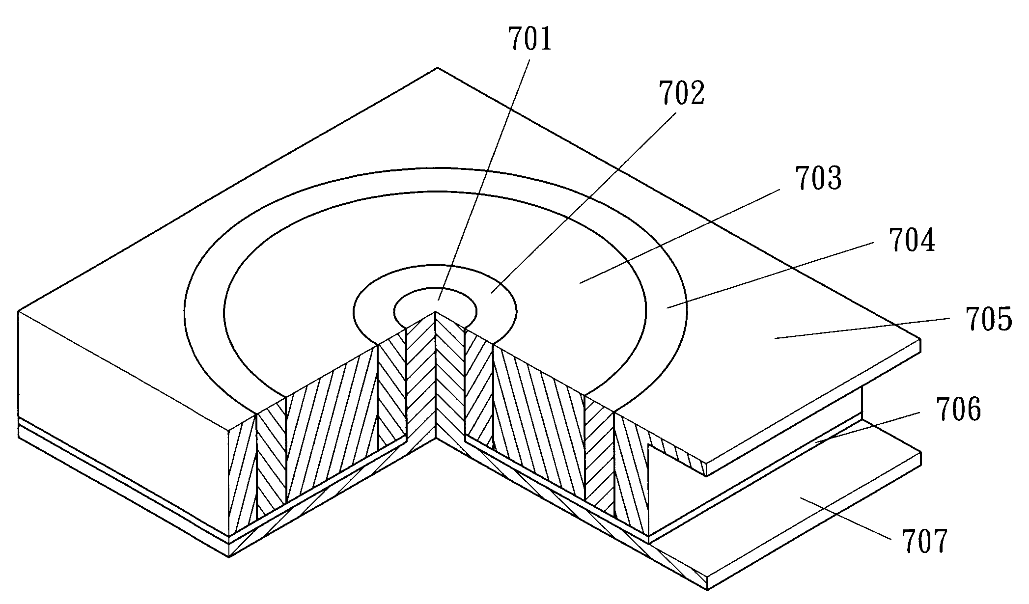
[0046]A solar cell power supply equipment consisting of coaxial solar cells arranged in a mesh layout as shown in FIG. 10. It has 100 rows of silicon P-I-N coaxial solar cells 1001 (referring to FIG. 7 for the structure). Each row has 100 coaxial solar cells 1001. Each coaxial solar cell 1001 has a power supply core electrode 1002. A common collector cathode 1003 is provided on the periphery for all the coaxial solar cells with a shared output terminal 1009 for the collector cathode. Each solar cell has a P-type annular semiconductor layer 1004, an I-type annular intrinsic semiconductor layer 1005, a N-type annular semiconductor layer 1006. There is also a planar insulation dielectric layer 1007 and a common anode plane 1008 to connect the bottom of the core electrode 1002 with a planar anode output terminal 1010 formed thereon.

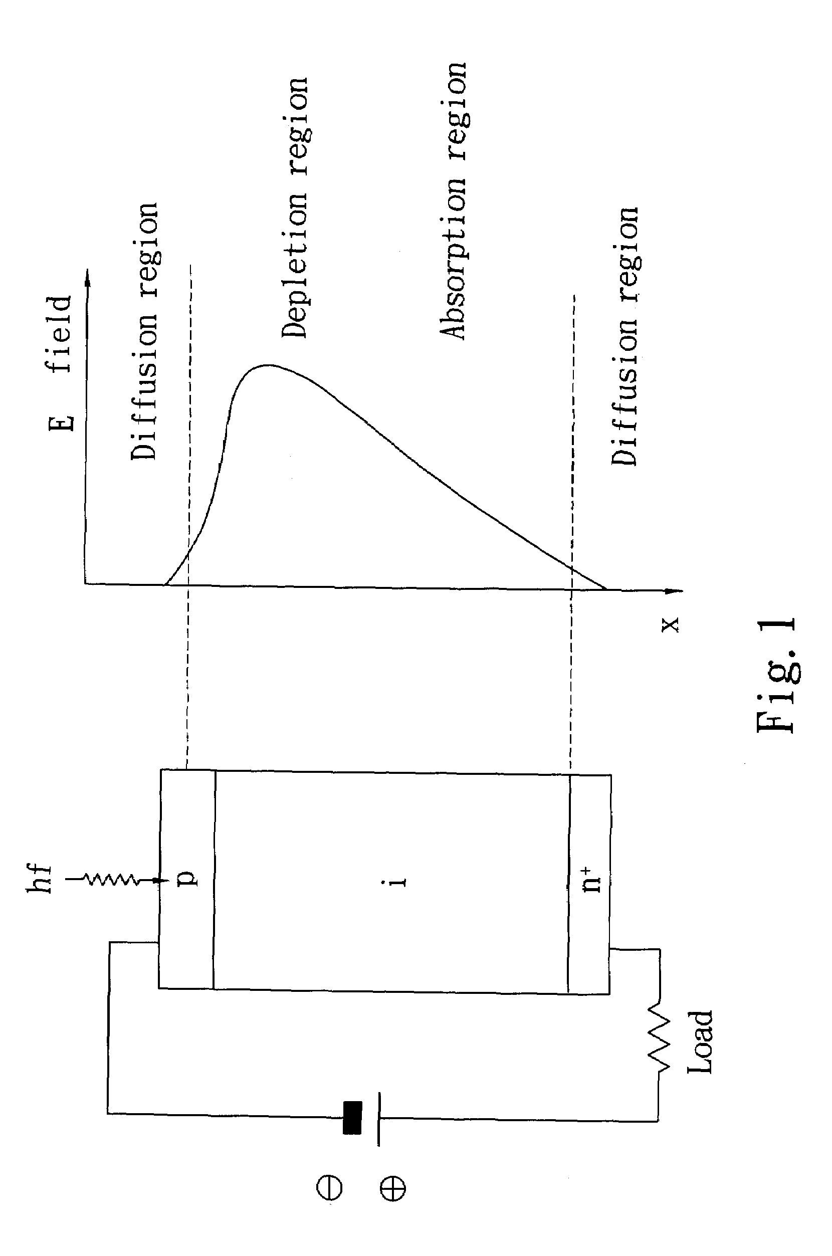
[0047]Based on the electric power generation principle of the coaxial solar cell previously discussed, the photons of various wavelengths directly project to...

embodiment 2

[0050]Refer to FIG. 11 for a second embodiment of the invention. It is a power supply equipment of a large unit area consisting of linear coaxial solar cells. It has 1000 linear coaxial solar cells 1101 (each at a length of 1 meter) coupled in parallel and laid on a same plane or a selected curved surface, such as an anchor seat 1102 of a streamline body surface of an air plane or vehicle. The power supply equipment thus formed can be coupled in a serial or parallel fashion according to minimum and maximum required voltage and current of usage to achieve power supply goals.

[0051]In the embodiment 2, each linear coaxial solar cell 1101 is formed by coaxial materials, including a reflective metal core anode 1103, a tubular N-type semiconductor layer 1104, a tubular I-type semiconductor layer 1105, a tubular P-type semiconductor layer 1106, a transparent tubular peripheral annular electrode conductive layer 1107, a surface protection layer 1108 plated with anti-reflection film on an ou...

embodiment 3

[0054]Refer to FIG. 13 for the continuous fabrication method of the linear coaxial solar cells used in embodiment 2 shown in FIG. 11. As the linear coaxial solar cell is fabricated by depositing layers of coaxial annular semiconductors or thin films of compounds, a conventional continuous drawing and coating process to form linear optical fibers can be adopted. First, a core conductor 1302 such as a stainless fine wire is drawn out from a feeding roll 1301; by passing through an annular N-type semiconductor layer depositing apparatus 1303 a first coaxial structure 1304 plated with N-layer is formed; through an annular I-type semiconductor layer depositing apparatus 1305 a bi-layer coaxial structure 1306 plated with the N-layer and I-layer is formed; through an annular P-type semiconductor layer depositing apparatus 1307 a triple-layer coaxial structure 1308 plated with N-layer, I-layer and P-layer is formed; through an annular electrode conductor depositing apparatus 1309 a tetra-la...


PUM


Abstract

A coaxial solar cell forces an exposed annular light receiving layers of a constant thickness to directly receive projection of light excitedly to generate pairs of electrons and holes that are driven by radial built-in electronic field formed on a PN junction to travel by the same distance paths to coaxial inner and outer electrodes. The photons directly enter an exposed drift region. The excited pairs of electrons and holes are separated by the even built-in electronic field to output current. Loss caused by crowding and recombination of diffusion current can be prevented. Photoelectric conversion efficiency improves without losing photon energy of short wavelengths projecting to the surface. The linear coaxial solar cell is fabricated by forming coaxial and annular semiconductor layers or compound films through deposition. Thus, it can be continuously fabricated by extending its length and mass production to reduce costs.

Description

FIELD OF THE INVENTION[0001]The present invention relates to a coaxial diode structure of solar cells to generate electric power and a continuous fabrication method of its linear coaxial solar cell structures.BACKGROUND OF THE INVENTION[0002]Generating electric power through solar energy is a vital technology at present due to increasing shortage of energy resources, especially to countries relying on importation of energy resources. How to lower fabrication cost of solar cells and increase photovoltaic conversion efficiency have become critical success factors of promoting alternative energy resources in large scales.[0003]The solar cell (also known as photovoltaic cell) can convert light radiation to electric energy through a commonly known photovoltaic effect. When photons of sun radiation hit an active region (such as a depletion region) of the solar cell, they are absorbed and pairs of electrons and holes are generated. These electrons and holes are separated from a built-in el...

Claims


Application Information

Patent Timeline
Patent Type & Authority Applications(United States)
IPC IPC(8): H01L31/00B05D5/12
CPCH01L31/035281Y02E10/50H01L31/06H01L31/03529
Inventor YANG, CHUN-CHU
Owner YANG CHUN CHU
Why Eureka
Try Eureka