Capillary electrophoresis using clear coated capillary tubes

a clear coating and capillary technology, applied in the field of capillary electrophoresis, can solve the problems of high cost and durability of soft fluoropolymer coated capillaries, the existing commercial ce systems with laser-induced fluorescence (lif) detection mechanism that use multiple capillaries/channels for high-throughput applications are complicated in design and operation of instruments, and achieve low cost and high structural integrity

Active Publication Date: 2010-05-06
QIAGEN SCIENCES LLC
View PDF4 Cites 12 Cited by
  • Summary
  • Abstract
  • Description
  • Claims
  • Application Information

AI Technical Summary

Benefits of technology

[0009]The present invention overcomes the drawbacks of polyimide coated capillaries for CE. The present invention provides a low cost, optically effective capillary tube having high structural integrity.

Problems solved by technology

Although a viable product for light guiding applications, soft fluoropolymer coated capillary has never achieved the low cost or durability desired for the large volume disposable multi-channel capillary gel cartridges of the capillary electrophoresis type instrument.
The existing commercial CE systems with laser-induced fluorescence (LIF) detection mechanism that use multiple capillaries / channels for high-throughput applications are complicated in design and operation of the instrument.
Soft fluoropolymer coated capillaries have not been used in such multi-channel applications.
This process is very labor intensive and requires a careful examination of the glass surface under high magnification after the removal process to make sure the window (glass surface) is completely free of the polyimide jacket or any other particulates.
Polyimide also fluoresces under visible light, which introduces further complications in the detection path.
Excessive heat or mechanical stresses applied at the detection zone during the removal of the coated materials / jacket also produces micro-cracks in the OD and ID of the fused silica tube, which are not visible or detectable under the high power magnification, which also can increase the background fluorescence affecting the overall Limit of Detection (LOD) in CE type instruments, such as DNA fragment analysis type CE instruments.

Method used


Image

  • Capillary electrophoresis using clear coated capillary tubes
  • Capillary electrophoresis using clear coated capillary tubes
  • Capillary electrophoresis using clear coated capillary tubes

Examples


Embodiment Construction

[0021]This invention is described below in reference to various embodiments with reference to the figures. While this invention is described in terms of the best mode for achieving this invention's objectives, it will be appreciated by those skilled in the art that variations may be accomplished in view of these teachings without deviating from the spirit or scope of the invention.

[0022]The present invention provides a low cost, optically effective capillary tube having high structural integrity, for use in capillary electrophoresis systems.

Overview of CE System

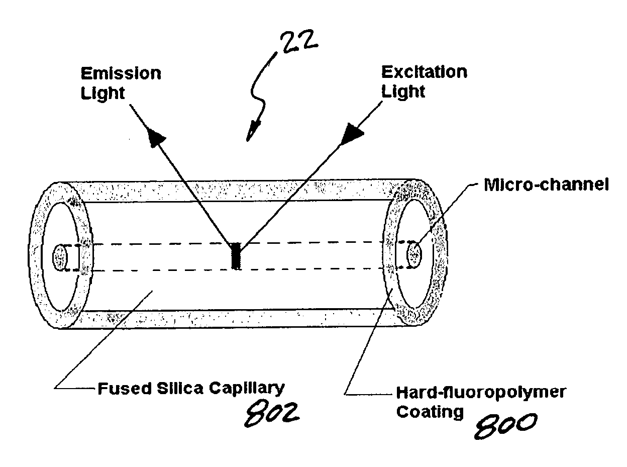
[0023]Capillary electrophoresis (CE) generally is a micro fluidic approach to electrophoresis (micro-channel device to simplify gel electrophoresis). Its greatest advantage is its diverse range of applications. CE technology is commonly accepted by the biotechnology industry specifically in the DNA or nucleic acid-based testing as a reliable, high resolution and highly sensitive detection tool. CE with laser-induced fluoresce...


PUM

PropertyMeasurementUnit
total currentaaaaaaaaaa
outer diameteraaaaaaaaaa

Abstract

A capillary tube having a hard, optically clear external coating or cladding. In one embodiment, the external clear coating comprises hard-fluoropolymer. The hard-fluoropolymer coating bonds to the fused silica glass, providing higher strength and superior static fatigue performance resulting in vastly improved bending flexibility. The thin hard-fluoropolymer coating of capillaries provides higher initial tensile strength, longer lifetime (resistance to stress corrosion or static fatigue) and superior ability to transmit excitation light and emitted light directly through the coating for fluorescence based detection.

Description

BACKGROUND OF THE INVENTION[0001]This application claims the priority of U.S. Provisional Patent Application No. 60 / 919,984 filed on Mar. 26, 2007. This Provisional Patent Application is fully incorporated by reference herein, as if fully set forth herein. All other applications, patents, documents and references identified in the disclosure herein below, are fully incorporated by reference as if fully set forth herein.[0002]1. Field of the Invention[0003]The present invention relates to capillary electrophoresis, and particularly an improved capillary tube for use to conduct capillary electrophoresis analysis.[0004]2. Description of Related Art[0005]Synthetic fused silica capillary tubing is widely used in the separation sciences, including the popular fields of Gas Chromatography, Capillary Liquid Chromatography, and Capillary Electrophoresis (CE). From its advent in the late 1970s, steady advances in product quality have emerged. Light guiding fused silica capillary tubing by app...

Claims


Application Information

Patent Timeline
Patent Type & Authority Applications(United States)
IPC IPC(8): G01N27/447
CPCG01N27/44704Y10T428/13G01N27/44721G01N27/447
Inventor AMIRKHANIAN, VAROUJ
Owner QIAGEN SCIENCES LLC
Why Eureka
Try Eureka