Four-cycle engine

Inactive Publication Date: 2010-05-13
HATAMURA KOICHI
View PDF11 Cites 28 Cited by
  • Summary
  • Abstract
  • Description
  • Claims
  • Application Information

AI Technical Summary

Benefits of technology

[0019]In the invention of claim 5, since the exhaust blowdown pressure of the first cylinder arrives at the exhaust port of the second cylinder near the intake stroke bottom dead center of the second cylinder, and exhaust valves of the second cylinder open ne

Problems solved by technology

For an exhaust gas of a diesel engine, reduction of nitrogen

Method used


Image

  • Four-cycle engine
  • Four-cycle engine
  • Four-cycle engine

Examples


first embodiment

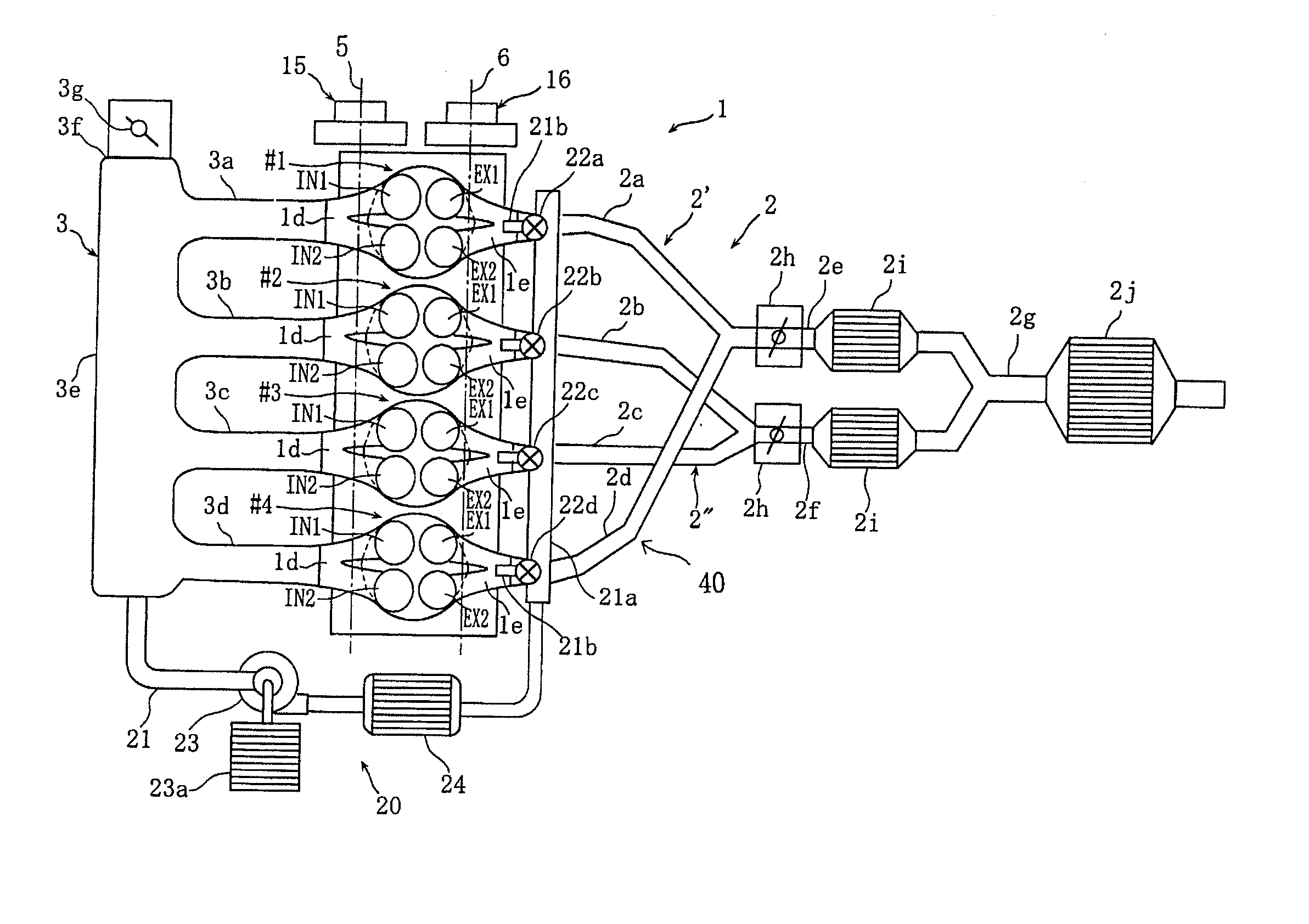
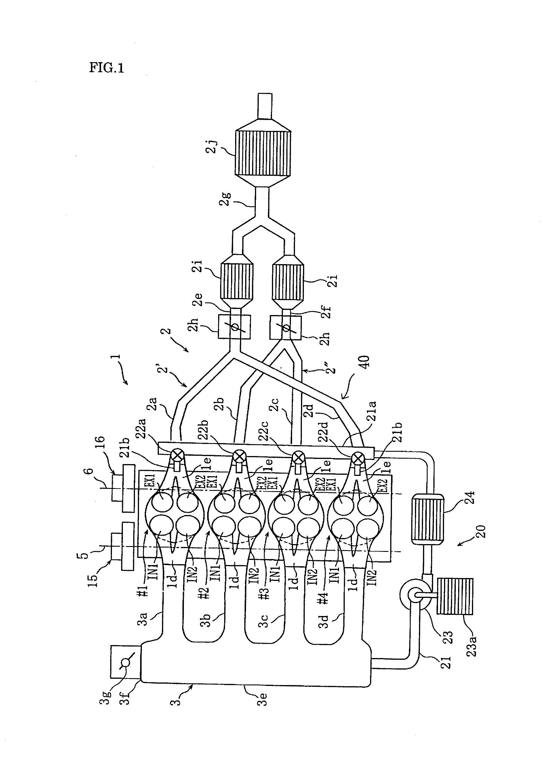
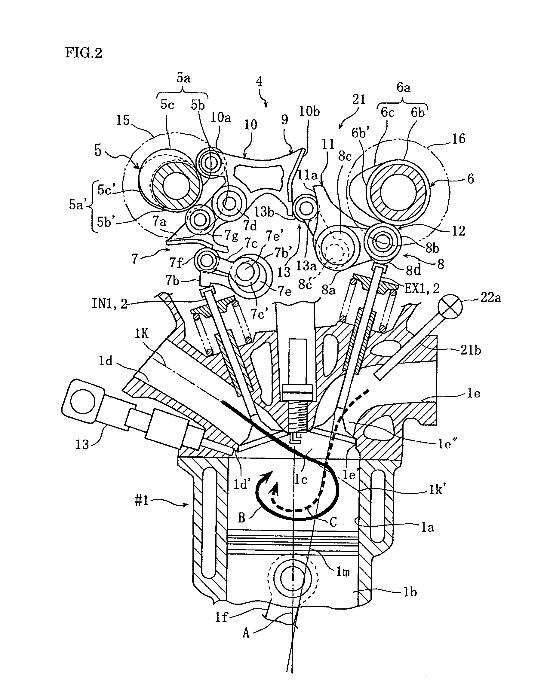
[0049]FIG. 1 to FIG. 7 are views for describing a four-stroke engine according to the present invention. FIG. 1 is an overall structural view. FIG. 2 is a cross-sectional side view of this engine. FIG. 3 is a schematic plan view of a valve system. FIG. 4 are schematic views of a switching system. FIG. 5 to FIG. 7 are graphs for describing operations.

[0050]In the drawings, numeral 1 denotes an HCCI engine based on a four-cylinder, four-valve DOHC gasoline engine. This engine 1 includes #1 cylinder to #4 cylinder. The #1 cylinder to #4 cylinder each have four valves in total: two intake valves IN1, IN2 and two exhaust valves EX1, EX2. Further, the engine 1 includes in-cylinder gasoline injection valves 13, and has a compression ratio set to 12 which is optimal for spark ignition combustion.

[0051]The order of ignition in the engine 1 is #1-#3-#4-#2 cylinders. The phase between the cylinders (ignition interval) is 180 degrees in crankshaft angles. Therefore, the phase between the #1 cyl...

second embodiment

[0090]In middle of the air introduction path 30 connected to a surge tank 3e of an engine 1 of the second embodiment, a main supercharger 31 driven by an electric motor or engine output is interposed, so as to supply fresh air compressed at a predetermined pressure to the engine 1. In addition, numeral 30a denotes a bypass detouring the main supercharger 31, numeral 30b denotes a bypass valve which opens / closes the bypass 30a, numeral 32 denotes an intercooler which decreases the temperature of compressed fresh air, and numeral 33 denotes an air cleaner.

[0091]Compressed fresh air from the main supercharger 31 is introduced into the cylinder bore of the #1 cylinder from the intake port 1d by opening of the intake valves in an intake stroke of the #1 cylinder. Near the end of this intake stroke, there is an overlap period in which the intake valves are open and the exhaust valves are open by EGR valve opening. Moreover, also due to the introduced fresh air being in a compressed state,...

third embodiment

[0095]FIG. 10 to FIG. 13 are views for describing the present invention. In these views, the same reference numerals as in FIG. 1 and FIG. 8 denote the same or corresponding parts.

[0096]In an engine 1 of the third embodiment, a merging pipe 2e of a first exhaust system 2′ and a merging pipe 2g of a second exhaust system 2″ are connected to a turbocharger 36 having one common variable nozzle turbine. An intercooler 35 is interposed in an air path 34 connecting an air discharge port of the turbocharger 36 and a surge tank 3e. Further, a pressure sensor 2r is disposed on an exhaust branch pipe 2a.

[0097]Further, the engine 1 of the third embodiment has a secondary air supply system 20 having the same structure as that of the above-described first embodiment. This secondary air supply system 20 includes a secondary air supply path 21 connecting the surge tank 3e and the exhaust ports 1e, an auxiliary supercharger 23 and an intercooler 24 interposed in the secondary air supply path 21, a...


PUM


Abstract

A four-stroke engine (1) structured to introduce fresh air and EGR gas into a cylinder (1a) includes a blowdown supercharging system (40) using a combustion chamber internal pressure when exhaust valves open in an expansion stroke of a first cylinder (hereinafter denoted as an exhaust blowdown pressure) for introducing EGR gas into a second cylinder from near a bottom dead center of an intake stroke to near a bottom dead center of a compression stroke of the second cylinder which is different from the first cylinder in combustion timing, and a secondary air supply system (20) supplying secondary air to an exhaust port (1e) of the second cylinder prior to arrival of the exhaust blowdown pressure at the second cylinder. The secondary air in the exhaust port and the EGR gas are supercharged into the second cylinder by the exhaust blowdown pressure from the first cylinder.

Description

TECHNICAL FIELD[0001]The present invention relates to a four-stroke engine structured to introduce fresh air (secondary air) and EGR gas into a cylinder, and more particularly relates to a four-stroke engine capable of securing the introduced amount of EGR gas while compensating reduction in the introduced amount of fresh air by secondary air with a simple structure. Note that in the present description, air introduced into a cylinder via an intake port is referred to as fresh air, and air introduced into a cylinder via an exhaust port is referred to as secondary air.BACKGROUND ART[0002]For an exhaust gas of a diesel engine, reduction of nitrogen oxides (NOx) and soot is one of the most important problems. Introduction of EGR gas is effective as a countermeasure for NOx in a medium load operation (acceleration), but the fresh air decreases and the soot increases in normal EGR. As a conventional technique capable of solving this problem, there is one using an exhaust blowdown pressur...

Claims


Application Information

Patent Timeline
IPC IPC(8): F02B33/00F02M25/07F01L1/34
CPCF01L1/08F01L1/181F01L1/20F01L1/267F01L13/0026F01L13/0063F01L2001/0537F01L2105/00F01L2800/10F01N3/22F01N3/32F02B1/12F02B23/104F02B29/0406F02B31/00F02B33/42F02B37/00F02B2023/106F02B2075/125F02D9/04F02D13/0207F02D13/0246F02D13/0273F02D23/00F02D41/0007F02D41/006F02D41/3035Y02T10/146Y02T10/144Y02T10/20Y02T10/47F01N13/107F02B33/38Y02T10/18F01N13/011F02M26/42F02M26/01F01L2305/00Y02T10/12Y02T10/40
Inventor HATAMURA, KOICHI
Owner HATAMURA KOICHI
Why Eureka
Try Eureka