

Hybrid Solar Cells with 3-Dimensional Hyperbranched Nanocrystals
- Summary
- Abstract
- Description
- Claims
- Application Information
AI Technical Summary
Problems solved by technology
Method used
Image

Examples
example 1
Preparation of Hyperbranched Semiconductor Nanocrystal Particles
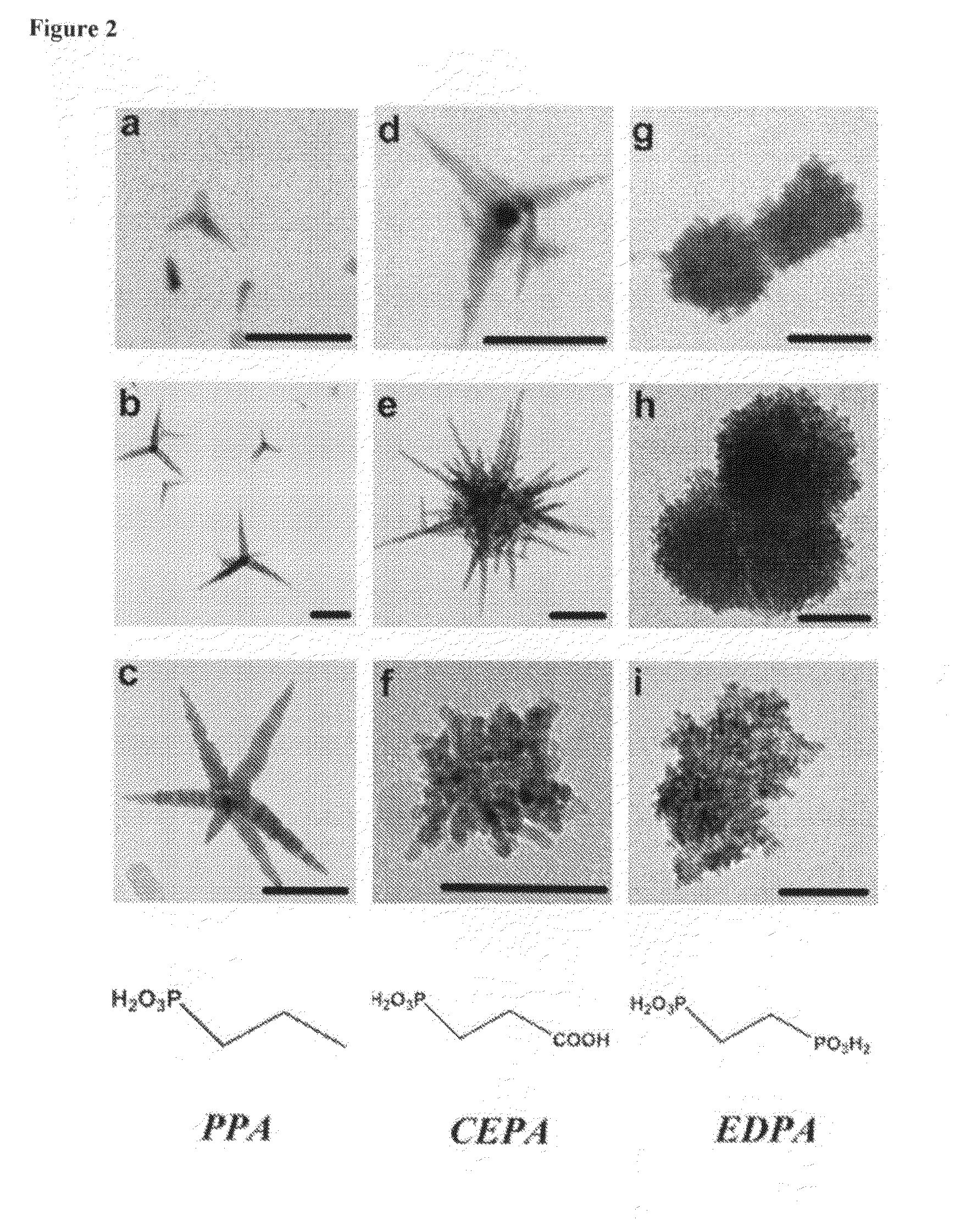
[0128]Basic protocol for synthesis of hyperbranched CdTe or CdSe particles. CdO (0.15 g, 1.1 mmol) was added in a mixture of TDPA (1 g, 3.59 mmole), CEPA (0.05 g, 0.32 mmole), and TOPO (3 g, 7.7 mmole), heated at 150° C. and kept under vacuum for 30 min to remove small amounts of water. Then the temperature was set at 335° C. and the brownish mixture was left under argon for 1 hour. This step resulted in a colorless solution due to the decomposition of the CdO and the formation of a Cd / phosphonic acid complex. TOP (1.2 g, 3.23 mmole) was injected and the temperature was adjusted to 335° C. Te and Se stock solutions were prepared by dissolving Te or Se in TOP (5%, 3.1% w / w, respectively). The mixture of Te:TOP (0.30 g, 0.117 mmole) or Se:TOP (0.30 g, 0.117 mmole) was injected into the hot reaction solution and the temperature was set to 330° C. (For all experiments the volume of the injected Te precursor was kept constan...
example 2
Photovoltaic Cell with Hyperbranched Semiconductor Nanocrystal Particles
[0130]Device Fabrication. All manipulations were performed using standard air-free techniques. To create cells based on hyperbranched nanocrystals, particles synthesized as described above were washed 2× by dissolution in toluene and subsequent precipitation with isopropanol, then suspended in 20 mL pyridine and stirred under reflux overnight for comprehensive ligand exchange. After reflux, the nanocrystals were precipitated with hexane, washed with toluene, and re-suspended in approximately 500 μL chloroform. These highly concentrated suspensions were ultrasonicated for ca. 10 minutes and combined with solutions of P3HT in pure chloroform. The blends were then spin-cast at 1500 rpm onto glass substrates coated with 150 nm ITO (Thin Film Devices Inc., resistivity 20 ohms / sq), and annealed on a hot plate at 120° C. for 60 minutes. Finally, samples were held at ca. 10− torr overnight, after which aluminum top elec...
example 3
Comparison of Hyperbranched Nanocrystal Photovoltaic Cell and Nanorod Photovoltaic Cell
[0133]FIG. 4 presents transmission electron micrographs of typical hyperbranched nanocrystals of cadmium selenide (CdSe) (FIG. 4c) and cadmium telluride (CdTe) (FIG. 4d). In one arrangement, hyperbranched CdSe crystals as shown in FIG. 4c were integrated into a matrix of poly(3-hexylthiophene) (P3HT) to produce hybrid solar cells. The conventional CdSe / P3HT donor-acceptor pair is well understood, and thus serves as a model system to understand behavioral changes due to the use of hyperbranched nanocrystals.
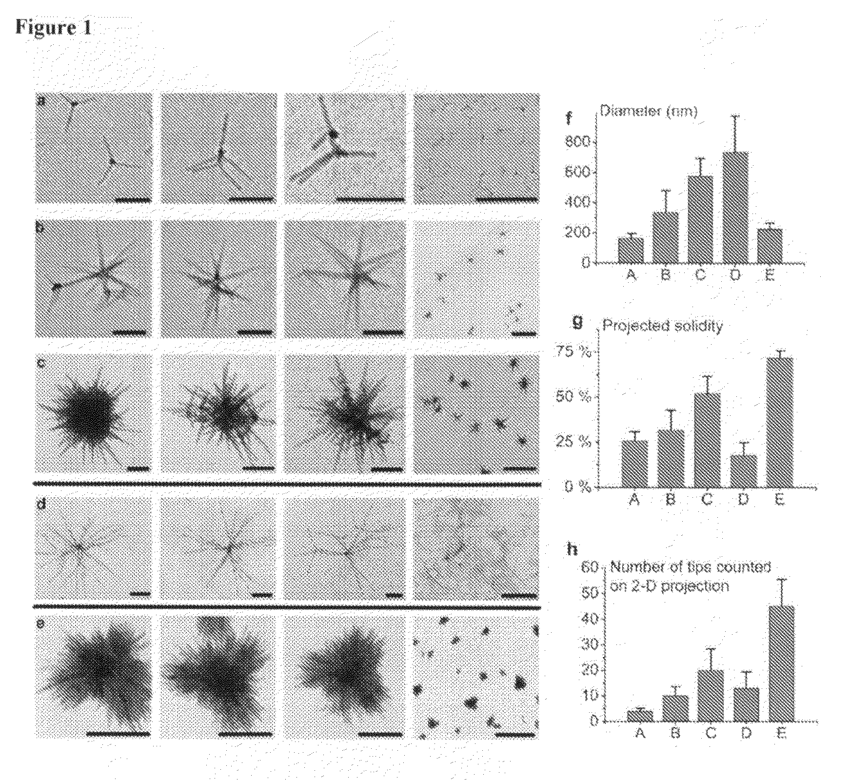
[0134]In order to explore the advantages of hyperbranched particles and the importance of their pre-formed percolation networks, a controlled comparison was made between nanorod-polymer solar cells and hyperbranched nanocrystal-polymer solar cells, each having the same percent of inorganic component. Transmission electron micrographs of these nanocomposite films are shown for six different conce...
PUM
| Property | Measurement | Unit |
|---|---|---|
| Ratio | aaaaa | aaaaa |
| Semiconductor properties | aaaaa | aaaaa |
Abstract
Description
Claims
Application Information