Honeycomb filter

a filter and honeycomb technology, applied in the field of honeycomb filters, can solve the problems of increasing the flow rate of exhaust gas passing through the partition walls, reducing the porousness of the partition walls, and increasing the pressure loss, etc., and achieves the effect of small pressure loss, excellent purification efficiency, and not easy to increase the pressure loss

Active Publication Date: 2010-06-03
NGK INSULATORS LTD
View PDF25 Cites 74 Cited by
  • Summary
  • Abstract
  • Description
  • Claims
  • Application Information

AI Technical Summary

Benefits of technology

[0011](c) As the pore diameters of the partition walls are small and the thicknesses of the partition walls are large, the DPF can efficiently trap the PM. Moreover, to prevent the entering of the PM in the inner portions (the pores) of the partition walls and shift to the cake filtering state early, the pore diameters of the partition walls are preferably set to small diameters. However, when the pore diameters of the partition walls are decreased and the partition walls are thickened, the increase of the pressure loss of the partition walls themselves before the PM deposition is caused, and this unfavorably lowers the engine performance.
[0067]The first, second and third honeycomb filter manufacturing methods of the present invention exhibit an excellent effect in that the first honeycomb filter of the present invention, which is an embodiment in which the surface layer contains 70 mass % or more of ceramic or metal fibers, can satisfactorily be prepared. The fourth honeycomb filter manufacturing method of the present invention exhibits an excellent effect in that the first honeycomb filter of the present invention, which is an embodiment in which the partition wall base material and the surface layer are constituted of the same material as the main component, can satisfactorily be prepared. The fifth honeycomb filter manufacturing method of the present invention exhibits an excellent effect in that the second honeycomb filter of the present invention can satisfactorily be prepared.

Problems solved by technology

However, a DPF to which such a honeycomb filter has been applied has the following problems to be solved.
Therefore, immediately after the start of the PM trapping, the substantial porosity of the partition walls decreases, the flow rate of an exhaust gas passing through the partition walls increases, and pressure loss sometimes rapidly increases.
Such a rapid increase of the pressure loss immediately after the PM trapping starts unfavorably lowers engine performance.
However, in the DPF having a conventional partition wall pore structure, the only PM deposited in the pores is naturally combusted, so that the pressure loss has hysteresis with respect to the total amount of the deposited PM, and the amount of the PM cannot precisely be estimated based on the pressure loss.
However, when the pore diameters of the partition walls are decreased and the partition walls are thickened, the increase of the pressure loss of the partition walls themselves before the PM deposition is caused, and this unfavorably lowers the engine performance.

Method used


Image

  • Honeycomb filter
  • Honeycomb filter
  • Honeycomb filter

Examples


example 1

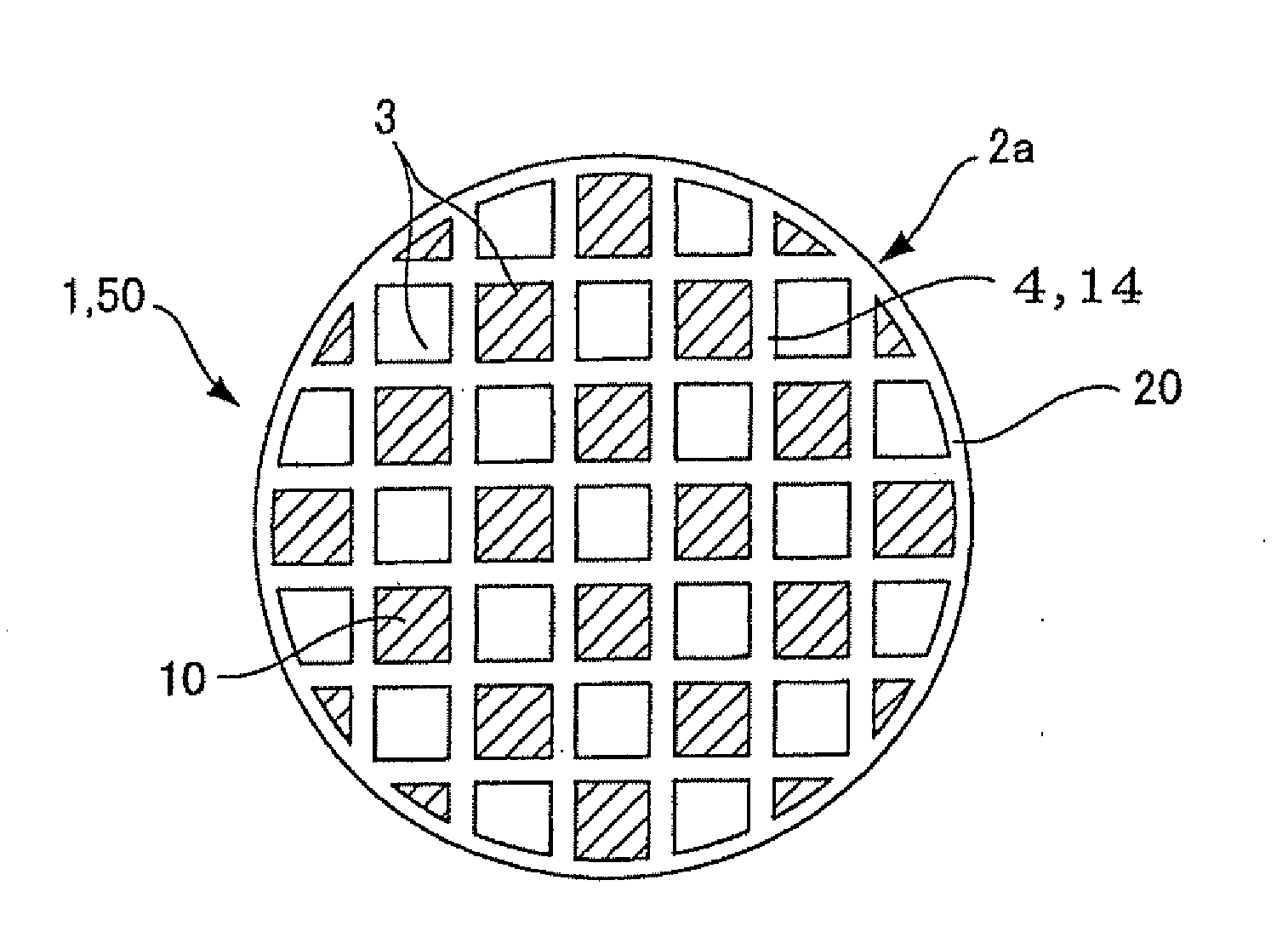
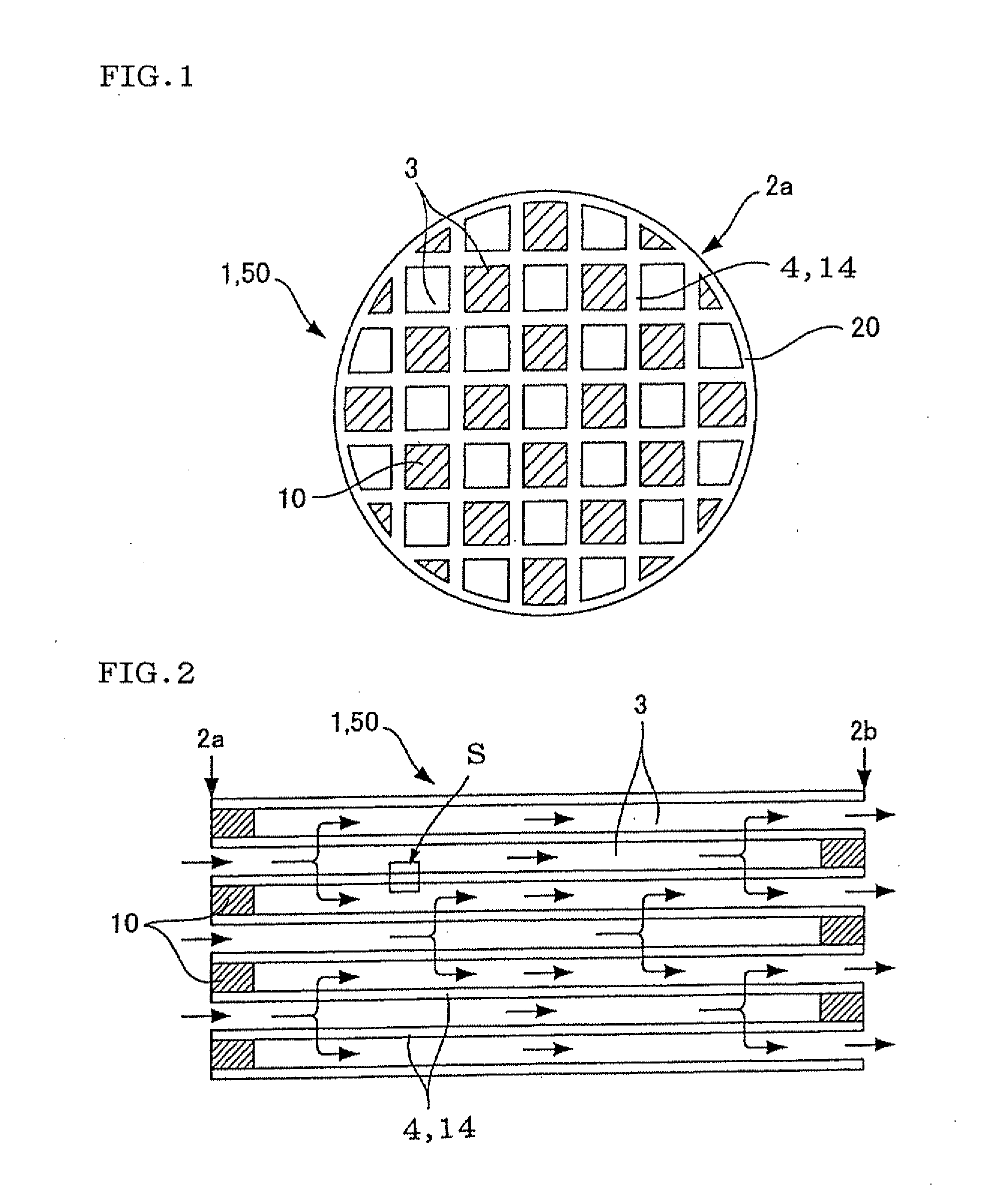
[0113][Preparation of Formed Honeycomb Article] As cordierite-forming materials, alumina, aluminum hydroxide, kaoline, talc and silica were used, and 13 parts by mass of a pore former, 35 parts by mass of a dispersion medium, 6 parts by mass of an organic binder and 0.5 part by mass of a dispersant were added to 100 parts by mass of cordierite-forming material, mixed and kneaded to prepare kneaded clay. Water was used as the dispersion medium, coke having an average particle diameter of 10 μm was used as the pore former, hydroxypropyl methyl cellulose was used as the organic binder, and ethylene glycol was used as the dispersant. Subsequently, the kneaded clay was extruded using a predetermined die to obtain a formed honeycomb article having a quadrangular cell shape and the whole columnar (cylindrical) shape.

[0114][Preparation of Plugged Honeycomb Structure] The formed honeycomb article was dried by microwave drying, and further completely dried by a hot air drier, and then both en...

examples 2 to 5

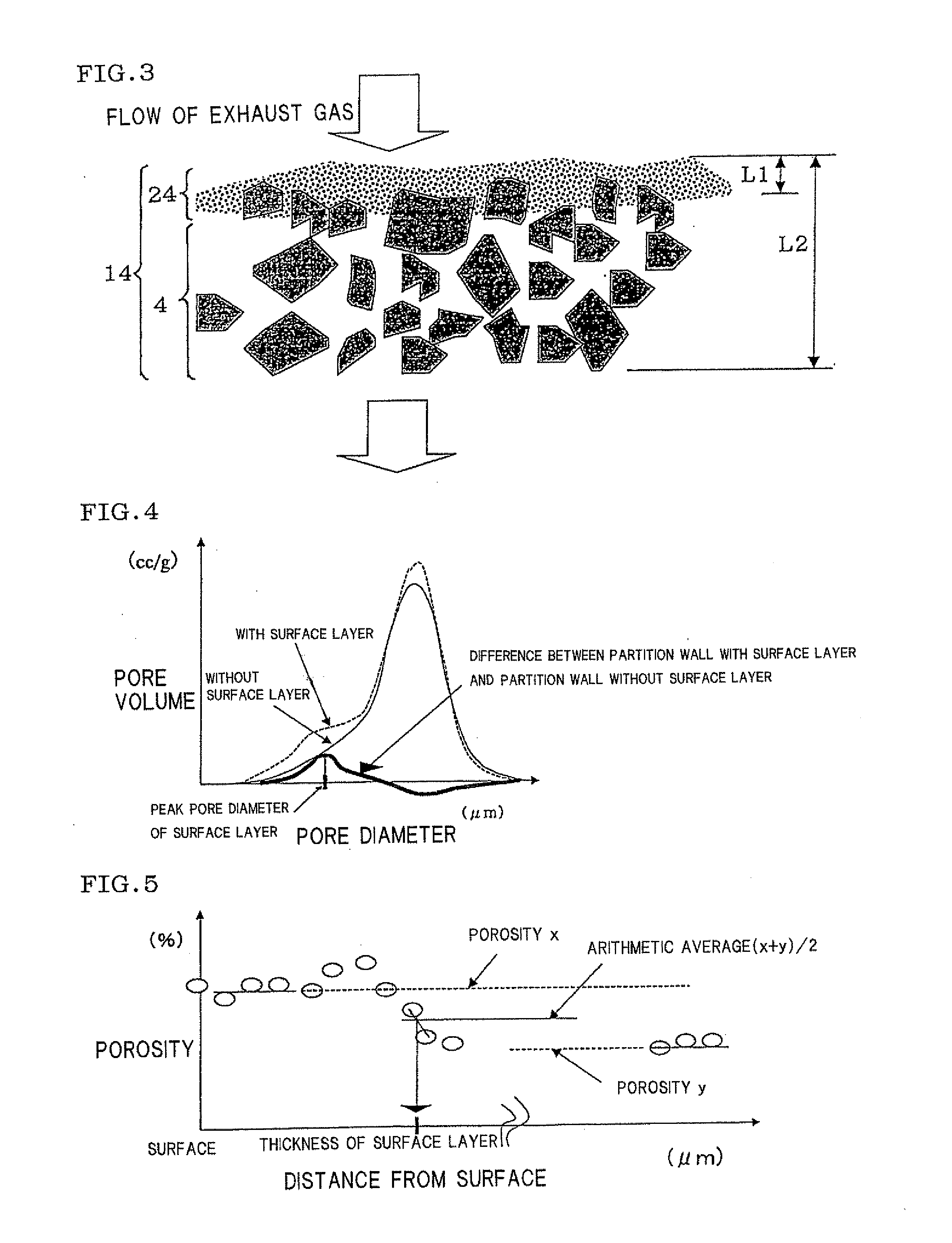
[0129]Honeycomb filters were prepared in the same manner as in Example 1 except that, to form a surface layer, a fibrous material was appropriately changed, and the atomization of slurry for the surface layer was appropriately adjusted to change a surface layer thickness L1, a surface layer peak pore diameter, a surface layer porosity, a surface layer fiber content, and surface layer thicknesses and masses in positions on an inlet side, in the center and on an outlet side, and the honeycomb filters were measured and evaluated with respect to items similar to those of Example 1. The results are shown in Table 1.

examples 6 , 7

Examples 6, 7

[0130]To prepare a plugged honeycomb structure (a formed honeycomb article), a die for extrusion was appropriately changed to change a cell density and a partition wall thickness L2. Moreover, to form a surface layer, a fibrous material was appropriately changed to change the peak pore diameter of the surface layer. Except for these respects, honeycomb filters were prepared in the same manner as in Example 1, and the honeycomb filters were measured and evaluated with respect to items similar to those of Example 1. The results are shown in Table 1.


PUM

PropertyMeasurementUnit
porosityaaaaaaaaaa
porosityaaaaaaaaaa
pore diameteraaaaaaaaaa

Abstract

A honeycomb filter including partition walls having a porous partition wall base material and a surface layer provided on only inflow side or both inflow and outflow sides of the partition wall base material, and satisfying the following conditions capable of using as a DPF. The surface layer has a peak pore diameter of from 0.3 μm to 20 μm (exclusive) being equal to or smaller than the average pore diameter of the base material; the porosity of from 60% to 95% (exclusive) when measured by mercury porosimetry being larger than that of the base material; and the thickness L1 of from 0.5% to 30% (exclusive) of the partition wall thickness L2; and mass per filtration area of from 0.01 mg / cm2 to 6 mg / cm2 (exclusive). The base material has an average pore diameter of from 10 μm to 60 μm (exclusive) and a porosity of from 40% to 65% (exclusive).

Description

TECHNICAL FIELD[0001]The present invention relates to a honeycomb filter which traps particulate matter in an exhaust gas.BACKGROUND ART[0002]There is an increasing need to remove, from exhaust gas, particulate matter included in the exhaust gas discharged from an internal combustion engine such as an engine for an automobile, an engine for a construction machine or a stational engine for an industrial machine, other combustion devices and the like in consideration of an influence on an environment. In particular, a regulation concerning the removal of the particulate matter (also referred to as the PM) discharged from a diesel engine tends to be strengthened worldwide. From such a situation, a diesel particulate filter (DPF) for trapping and removing the PM attracts attention.[0003]Examples of the DPF include a honeycomb filter provided with porous partition walls which separate and form a plurality of cells functioning as fluid flow paths. Predetermined cells each having one end o...

Claims


Application Information

Patent Timeline
Patent Type & Authority Applications(United States)
IPC IPC(8): B01D39/20B32B3/12B01D53/94B01D46/24C04B35/64
CPCB01D46/2425B01D46/2429B01D46/2451B01D46/2466B01D46/247F01N3/0222B01D2046/2433B01D2046/2437B01D2046/2496B01D2279/30B01D46/2474B01D46/24492B01D46/24491B01D46/2498B01D46/2482
Inventor MIZUNO, YUKIONODA, NAOMIYAMADA, TOSHIOMIYAIRI, YUKIONAKANE, YUKARINOGUCHI, YASUSHI
Owner NGK INSULATORS LTD
Why Eureka
Try Eureka