[0006]It is an object of the invention to provide an electronic device and a method for DC-DC conversion having reduced EMI emission without a need of external components or much additional
silicon area.
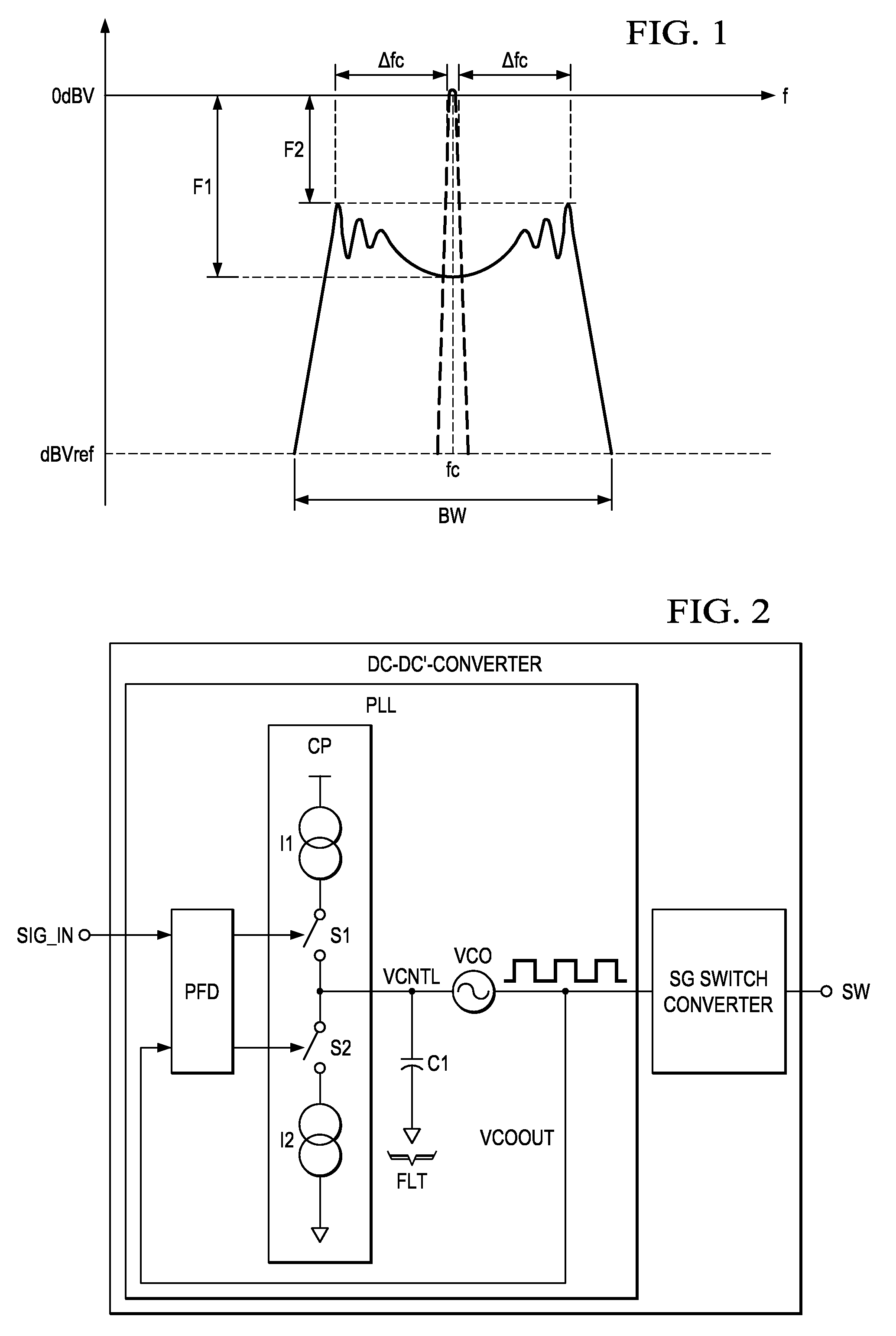
[0008]An electronic device that is configured in accordance with advantageous aspects of the invention includes a DC-
DC converter that is configured to be used in slave and master mode. The electronic device includes a phase locked loop (PLL). When the electronic device is configured in slave mode (first configuration), the PLL is enabled to synchronize the internal DC-
DC converter clock to an
external reference clock. When the electronic device is configured in master mode (second configuration), the phase locked loop can be disabled or can be adapted to generate a modulation
signal for performing a
spread spectrum modulation of the DC-DC converter internal clock. This internal clock, that is accessible at an output pin (often referred to as “switch pin”) of the DC-DC converter (or electronic device), can be used as
master clock (or reference clock) to synchronize additional switch converters present in the
system and configured as slaves. The phase locked loop may include a controlled oscillator (e.g. a
voltage controlled oscillator), a filter having an integration
capacitor coupled to the control input of the controlled oscillator, a charge pump, and a phase frequency
detector. The output of the controlled oscillator may be the internal clock of the DC-DC converter. The controlled oscillator, the filter, the charge pump and the phase frequency
detector may be coupled in a first configuration in the slave mode to operate as a
normal phase locked loop for
synchronizing the internal DC-DC converter clock to an
external reference clock (or
master clock). Furthermore, there may be a
comparator which monitors the control voltage of the oscillator when the electronic device is configured as master in the master mode of the electronic device. The phase frequency
detector may then be configured to be switched off. Instead of the phase frequency detector, the comparator may then be used to control the charge pump to perform a modulation of the
control signal of the controlled oscillator by charging and discharging an integration capacitor of the
loop filter. In that way, the
low frequency signal required for the modulation of the internal DC-DC clock is obtained. Accordingly, most of the components of the phase locked loop (charge pump, integration capacitor and
voltage controlled oscillator) together with the comparator may be used in the master configuration (or second configuration) to modulate the internal clock of the DC-DC converter. This provides the
advantage that only very few additional components, circuitry and modifications are required to change a conventional phase locked loop into a control loop which is capable of performing an SSC modulation of the DC-DC converter clock. This reduces the size of the required
electronic circuit and thereby manufacturing costs of the electronic device. This kind of implementation of the SSC modulation is possible due to the relaxed
jitter requirements in switch converter (DC-DC converters) applications with respect to the much higher
jitter requirements of communications and
microprocessor systems.
[0011]The controlled oscillator (or
voltage controlled oscillator) may be a modified
RC oscillator. It may comprise an oscillation capacitor Cosc, an oscillation
resistor Rosc and a comparator. The capacitor Cosc is charged to a voltage VREFOSC at a rate defined by Rosc and Cosc (i.e. by the Rosc x Cosc
time constant). The comparator monitors the
capacitor voltage and discharges it when VREFOSC has been reached. This is an advantageous way to generate a clock (comparator output) and at the same time a ramp or sawtooth waveform (
capacitor voltage) required for DC-DC converters using
pulse width modulation. The optimum method of modulating the clock frequency in order to perform the
spread spectrum clocking (SSC) is varying slightly the slope of the generated ramp. In order to vary the ramp slope, a controlled
current source may be implemented in the electronic device and configured to supply a current to the oscillation capacitor which is proportional to the control
signal.
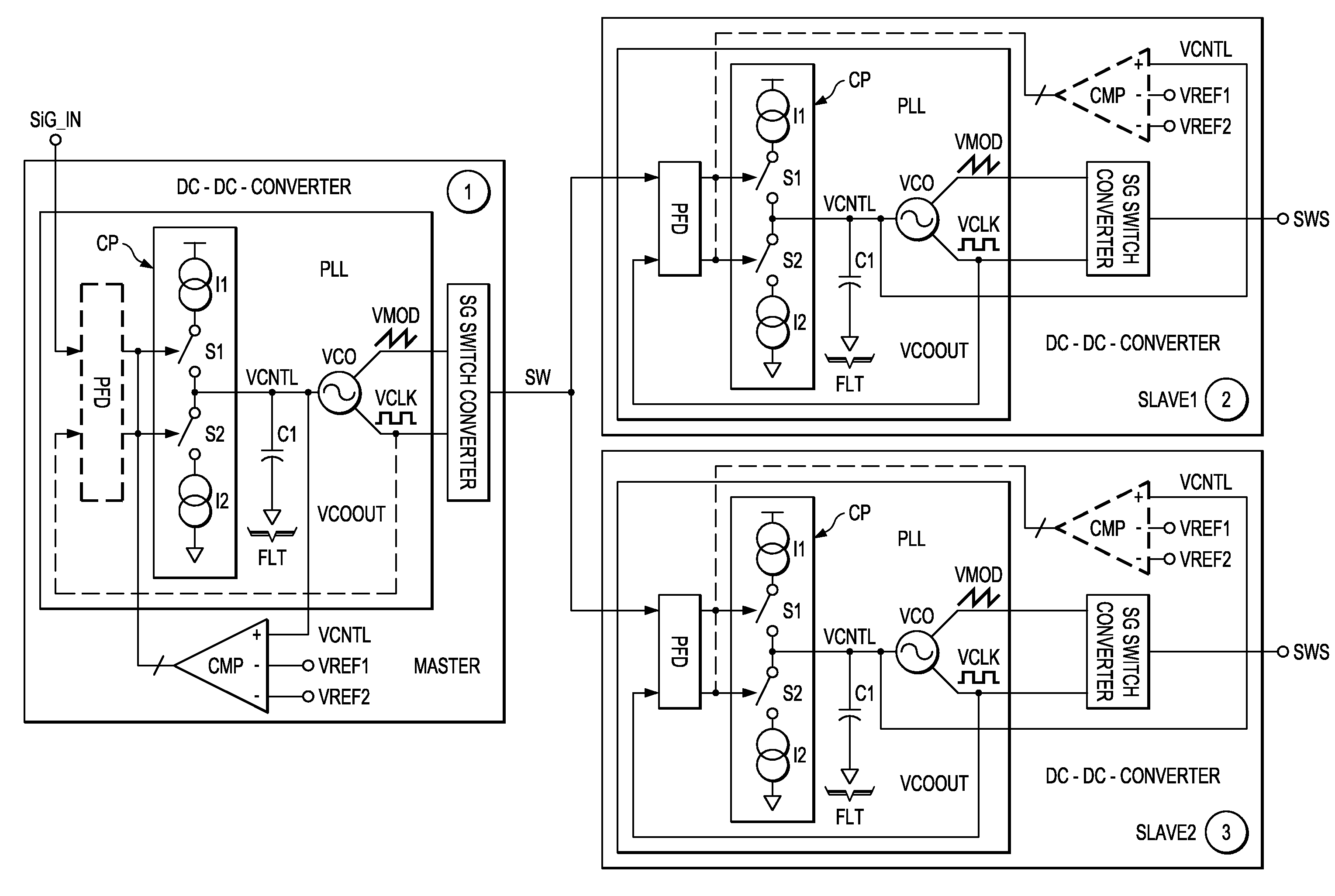
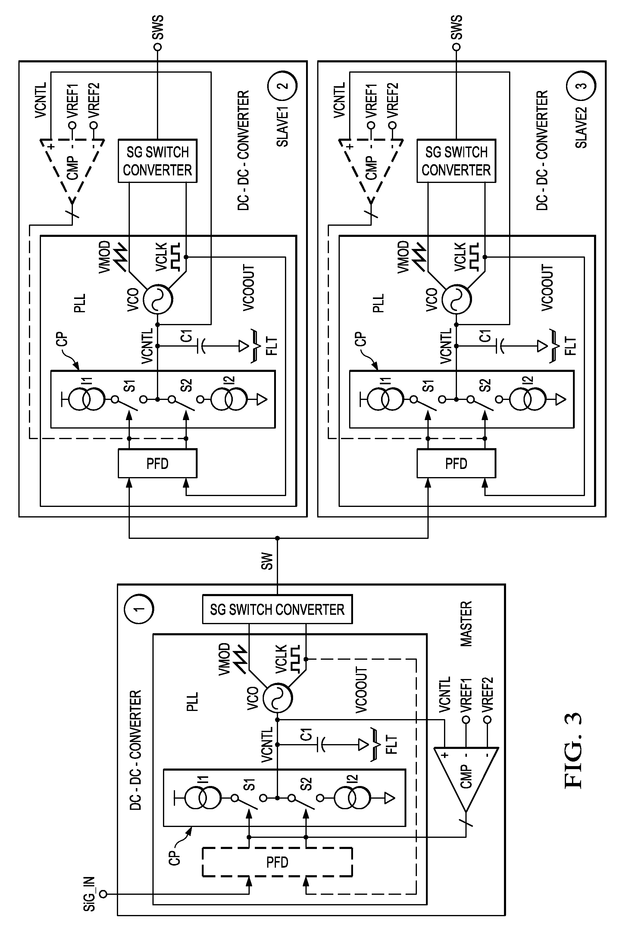
[0012]The invention also provides a
system including at least two electronic devices configured in accordance with aspects of the invention, i.e., for example a first DC-DC converter and a second DC-DC converter. One DC-DC converter may be configured to operate in master mode and one or more other DC-DC converters may be configured to operate in slave mode. The DC-DC converters running in slave mode may be synchronized to the
master clock (modulated
clock signal) from the DC-DC converter running in master mode. Using
spread spectrum clocking and synchronization together prevents generation of
intermodulation bands that can fall into audio frequencies and cause interference. As set out above, the modulation stage may be implemented by the first control loop. In other words, the first control loop in the master DC-DC converter performs the
spread spectrum modulation of the frequency of the first
clock signal and the slave devices synchronize to the first clock frequency. This means that only few additional components are required to implement the modulation stage in the master device, which simplifies production and reduces
chip area. The bandwidth of the phase locked loops of the DC-DC converters used in slave mode should be wide enough in order to be able to track the spread spectrum clocking modulation from the master DC-DC converter. The PLL function of the master DC-DC converter can be disabled and most of the PLL blocks can be reused to perform an SSC modulation of the
switching frequency. Then, the SSC function can be enabled only for the DC-DC converter which is the master device and the synchronization function can be enabled only for the DC-DC converter or DC-DC converters which are in slave mode. Therefore, no significant additional
silicon area is required to obtain the spread spectrum clocking function.
[0014]The invention also provides a method of
synchronizing a first
clock signal having a first clock frequency controlled by a first control loop and a second clock signal having a second clock frequency controlled by a second control loop. The first and second clock signals may be configured to be used for voltage conversion. Furthermore, a control signal is generated to perform a
spread spectrum modulation of the first clock frequency, and the second clock signal is synchronized with the spread spectrum modulated first clock signal. Performing both a synchronization of the first clock signal and the second clock signal and a spread spectrum clocking of the first clock signal allows
intermodulation products in sensitive frequency bands such as the audio band to be reduced, which would otherwise cause interference with required signals. Using just a part of the first phase locked loop, for example, and switching off the functionality of the phase frequency detector means that no extra circuitry is required in the DC-DC converter. Therefore, existing designs can be simply adapted to perform the method of the present invention without extra cost and without taking up additional space on the circuit.

