Capacitive touch panel, manufacturing method therefor and liquid crystal display apparatus provided with the touch panel

a manufacturing method and touch panel technology, applied in the direction of paper/cardboard containers, instruments, other domestic objects, etc., can solve the problems of decreasing optical characteristics (transmittance), durability of laminated structures, and insufficient optical characteristics or durability of resistive touch panels for certain applications, etc., to achieve high quality display, low cost, and good performance

Inactive Publication Date: 2010-07-01
SUMITOMO METAL MINING CO LTD
View PDF3 Cites 37 Cited by
  • Summary
  • Abstract
  • Description
  • Claims
  • Application Information

AI Technical Summary

Benefits of technology

[0038]In this way, the low cost production process can be adopted, and also the capacitive touch panel and

Problems solved by technology

However, optical characteristics or durability of such a resistive touch panel is not necessarily sufficient for certain applications.
That is, because the resistive touch panel has a configuration where an air layer is configured between two sheets of the transparent conductive films, there is a problem of decreasing optical characteristics (transmittance) by generation of light reflection at the interface thereof, caused by difference of refractive index of the transparent conductive film and the air layer.
In addition, because of a configuration where pressing is repeated with the tip part of the pen for data input etc. to a laminated structure having the air layer at the intermediate region, there is also a problem o

Method used


Image

  • Capacitive touch panel, manufacturing method therefor and liquid crystal display apparatus provided with the touch panel
  • Capacitive touch panel, manufacturing method therefor and liquid crystal display apparatus provided with the touch panel
  • Capacitive touch panel, manufacturing method therefor and liquid crystal display apparatus provided with the touch panel

Examples


example 1

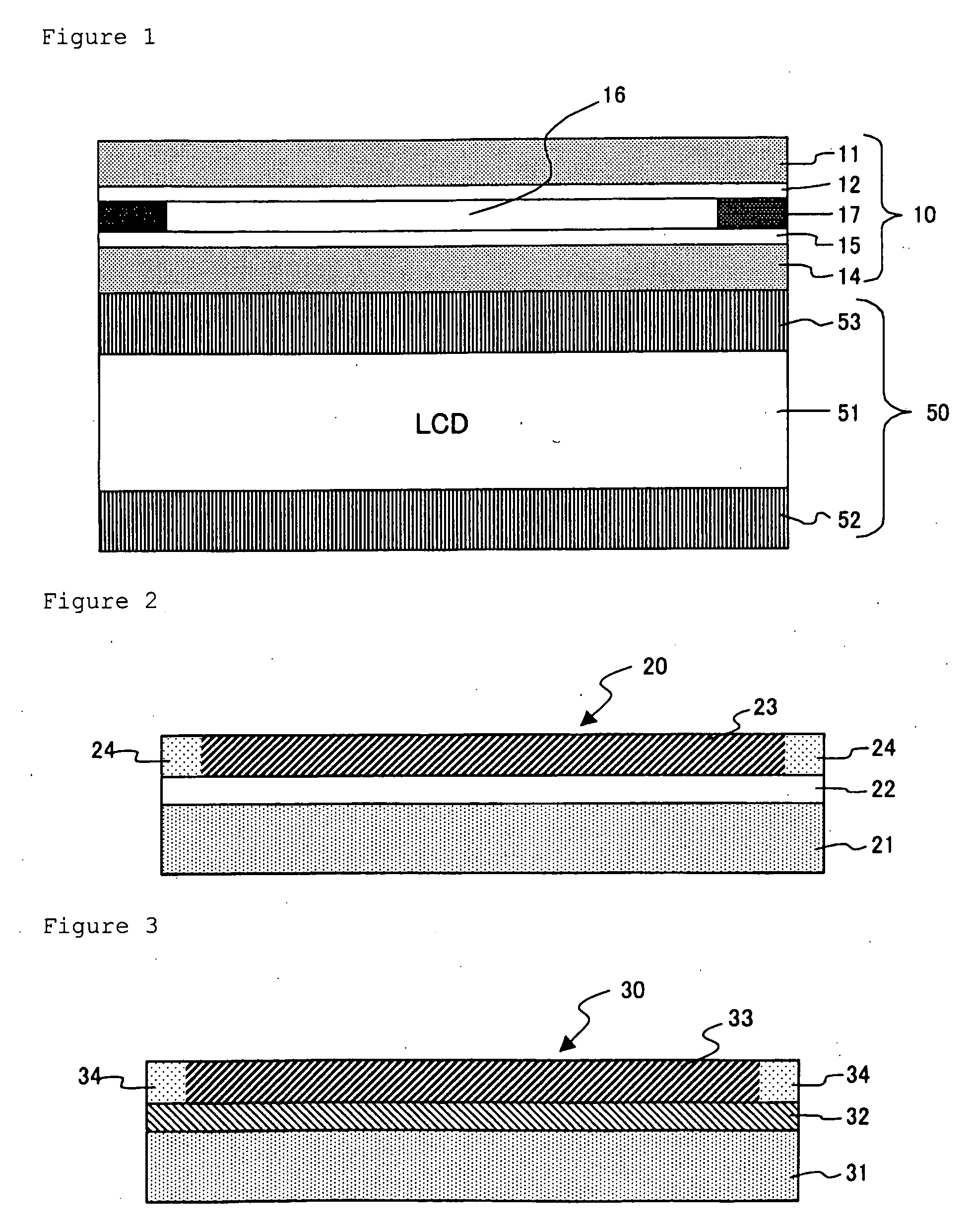
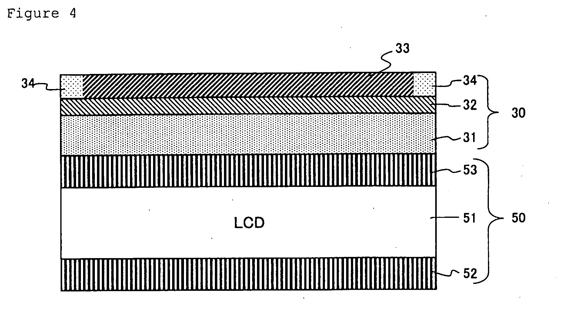
[0098]The capacitive touch panel of the present invention having a configuration of FIG. 3 was prepared. As a transparent substrate, a soda lime glass substrate of 0.5 mm thickness (hereafter an SLG substrate) formed with a silicon oxide thin film was prepared, and a target composed of an oxide having indium oxide, as a main component, where gallium content is 0.05 as atomic ratio of Ga / (In+Ga+Sn), and tin content is 0.09 as atomic ratio of Sn / (In+Ga+Sn), was installed at a direct current magnetron sputtering apparatus (manufactured by ANELVA Corp.), equipped with a direct current power source not having arcing suppression function.

[0099]After that, by arranging the substrate just above the sputtering target, that is, at standing-still facing position, evacuating the sputtering apparatus at room temperature without heating and applying a direct current power of 200 W, direct current plasma was generated and sputtering was carried out to deposit the transparent conductive film onto t...

example 2

[0101]The capacitive touch panel having a configuration of FIG. 3 was prepared by the similar process as in Example 1, except that target composition was changed to have indium oxide, as a main component, where gallium content is 0.10 as atomic ratio of Ga / (In+Ga+Sn). It was confirmed that the transparent conductive film had the same composition as the target, and generation phase of the film was amorphous, as an investigation result with X-ray diffraction measurement. Film thickness of this transparent conductive film was 15 nm, and surface resistance was 1000Ω / □.

[0102]When a thermal load of 500° C. in air was applied in the in the formation process of member for position detection of the capacitive touch panel, surface resistance of the above transparent conductive film increased from 1000Ω / □ to 1500Ω / □, however, it never exceeded 1500Ω / □, therefore there was no problem in the position detection of the capacitive touch panel, and the display of the liquid crystal display apparatus...

example 3

[0103]The transparent conductive film was formed onto the soda lime glass substrate (SLG substrate) formed with the silicon oxide thin film, similarly as in Example 1. The transparent conductive film was an amorphous transparent conductive film composed of an oxide having indium oxide, as a main component, where gallium content is 0.05 as atomic ratio of Ga / (In+Ga+Sn), and tin content is 0.09 as atomic ratio of Sn / (In+Ga+Sn). Film thickness of this transparent conductive film was 12 nm, and surface resistance was 1000Ω / □.

[0104]Then, this transparent conductive film was subjected to heat treatment in air at higher temperature 350° C. than crystallization temperature 330° C. of this transparent conductive film. As a result, the transparent conductive film crystallized, however, surface resistance increased to 1200Ω / □. Subsequently, an antireflection film composed of a silicon oxide thin film and a niobium oxide thin film was formed.

[0105]After that when a thermal load of 500° C. in ai...


PUM

PropertyMeasurementUnit
Temperatureaaaaaaaaaa

Abstract

A capacitive touch panel, which is capable of providing high quality display, without a problem of position detection, even in the case where a production process with lower cost and higher heat load is adopted, by application of a transparent conductive film with high heat resistance; a manufacturing method therefor, and a liquid crystal display apparatus.
A capacitive touch panel having a structure where at least a transparent conductive film and a dielectric layer are laminated onto a transparent substrate, and a member for position detection comprising at least a wiring portion for position detection along with a electrodes for position detection is arranged at said substrate frame portion, characterized in that the transparent conductive film is composed of an oxide having indium oxide as a main component and containing gallium and tin; and this is provided by a method for producing a capacitive touch panel, characterized in that after forming an amorphous transparent conductive film composed of an oxide having indium oxide as a main component and containing gallium and tin onto the transparent substrate or the like.

Description

BACKGROUND OF THE INVENTION[0001]1. Field of the Invention[0002]The present invention relates to a capacitive touch panel, a manufacturing method therefor, and a liquid crystal display apparatus provided with the touch panel, and in more detail, the present invention relates to a capacitive touch panel, which is capable of providing high quality display without a problem of position detection, even in the case where a production process with lower cost and higher heat load is adopted by application of a transparent conductive film with high heat resistance, a manufacturing method therefor, and a liquid crystal display apparatus.[0003]2. Description of the Prior Art[0004]A touch panel is one for carrying out an operation of an apparatus and a system by a method that an operator contacts with a transparent surface installed at the upper part of the display screen with a pen or a finger. Because operation by direct contact to a view screen is direct and intuitive, the touch panel has b...

Claims


Application Information

Patent Timeline
IPC IPC(8): G06F3/041B32B37/00
CPCB32B2037/246B32B2307/202B32B2307/204B32B2457/202G06F3/044Y10T156/10G06F3/0445G02F1/13338G06F3/0412G06F2203/04103
Inventor NAKAYAMA, TOKUYUKIABE, YOSHIYUKI
Owner SUMITOMO METAL MINING CO LTD
Why Eureka
Try Eureka