Optimised energy storage device
a technology of energy storage and energy storage device, which is applied in the direction of battery, sustainable manufacturing/processing, cell components, etc., can solve the problems of lead-acid batteries failing prematurely, forming a layer of lead sulphate on the surface, and battery used in these vehicles still suffer from a number of problems, so as to reduce the electrical resistance of the electrode, enhance mechanical strength, and increase the effect of weigh
- Summary
- Abstract
- Description
- Claims
- Application Information
AI Technical Summary
Benefits of technology
Problems solved by technology
Method used
Image
Examples
example 1 — e1
Example 1—E1
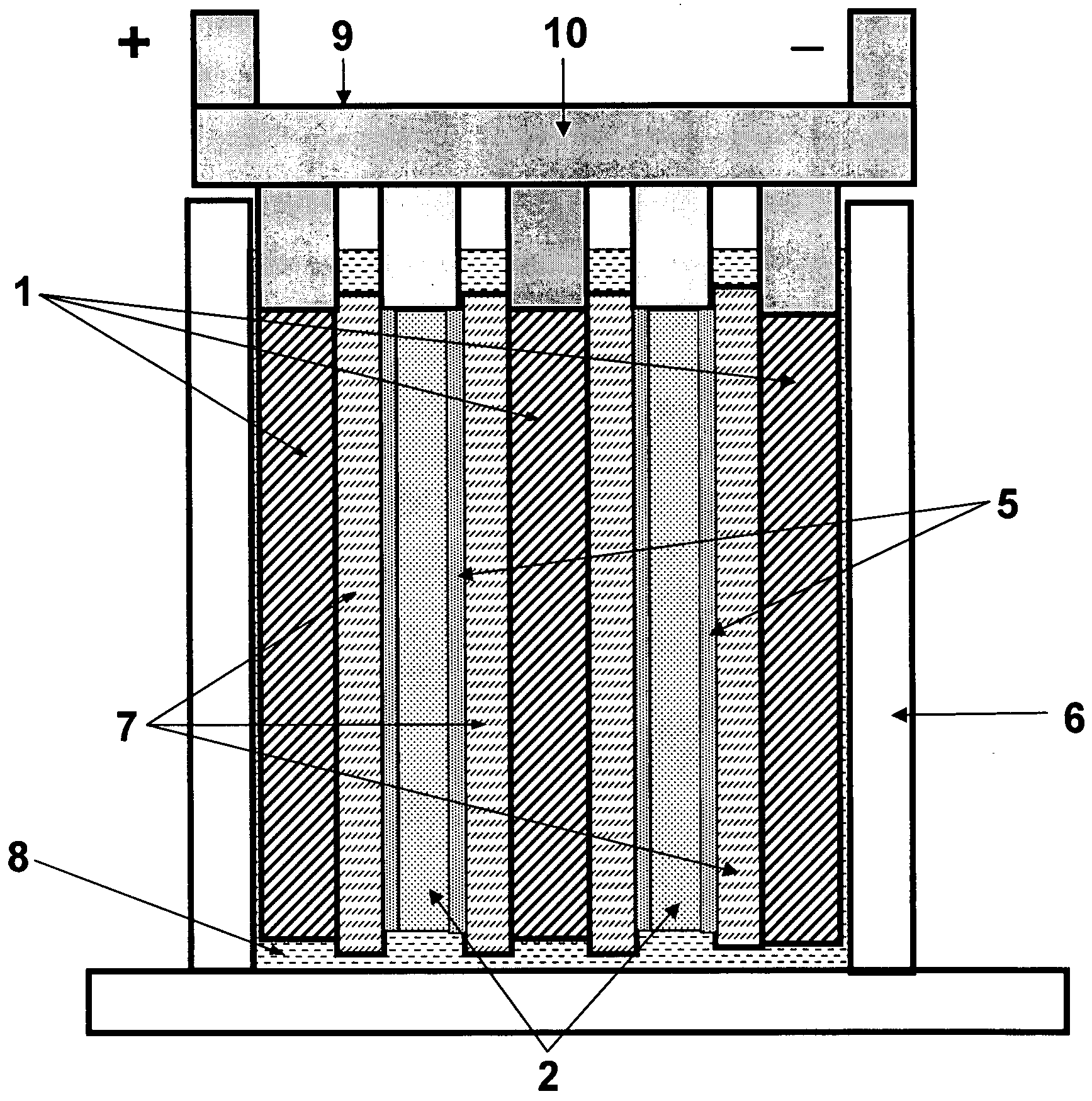
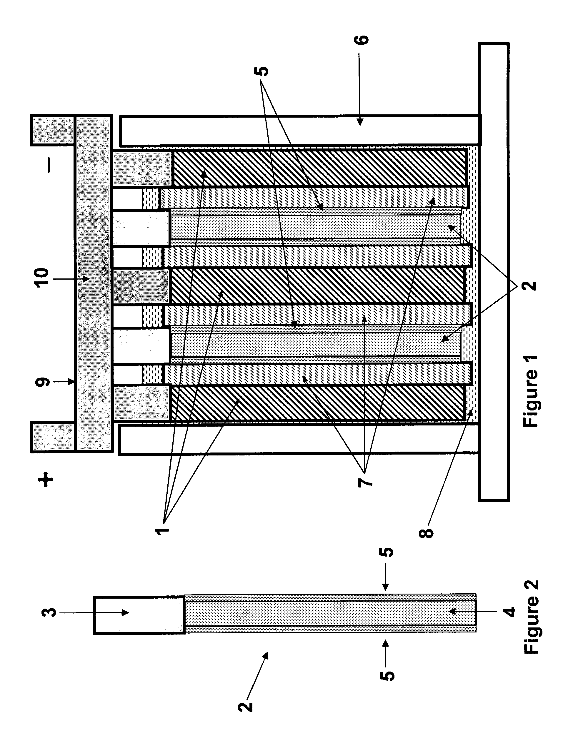
[0075]A monoblock battery (87 mm W×150 mm L×110 mm H) of 6 cells in a VRLA arrangement was constructed with following components, processes and conditions;
[0076]Negative electrode: grid (Pb with 0.1% Ca) of 76mm W×76 mm H×1.4 mm thickness, 5 plates / cell
[0077]Aqueous mix (density 4.0) of lead oxide, expander, polyester fiber and sulfuric acid was applied to grids, cured, dried and then tank formed according to conventional methods.
[0078]The capacitor mix is composed of
Carbon black (furnace black)43 mass partsActive carbon (SSA 2300 m2 / g)38Polyester fiber (20 μm diameter, 5aspect ratio 150)Chloroplane rubber10CMC 4Water280□ based onthe 100 massparts of 100%solids content.
[0079]The mix is applied onto both sides of all formed plates by the doctor blade method and dried. Capacitor mass was 5% of total negative active mass(dry base) with 75% porosity.
[0080]Positive electrode: grid (Pb with 0.035% Ca, 0.007% Ba, 1.8% Sn) of 76 mm W×76 mm H×1.7 mm thickness, 4 plates / cell.
[0081...
reference example 1
[0093]In place of the negative electrode of Example 1, the negative electrodes were prepared to have a type of reference configuration as follows:[0094]A half area of the negative electrode was pasted with the battery mix, and the other half was pasted with the capacitor mix. The halves were a left-hand side and a right-hand side, coated on both faces with the battery material, or capacitor material, respectively.
reference example 2
[0095]In place of the container used in Example 1, new larger one (87 mmW×220 mmL×110 mmH) was used to insert the following plate group composed of the battery and capacitor portions keeping the same group pressure of 60 kPa. The battery portion was the same to above E1 and capacitor portion was composed of the 5 capacitor negative electrodes and 4 positive electrodes alternatively arranged in series and interleaved with AGM of 0.5 mm thickness. The both electrodes were constructed with 0.6 mm thick lead sheet substrates with 45% punched-openings by coating capacitor and positive battery mixes, respectively and the dry thicknesses of the negative and positive electrodes were about 0.9 and 0.7 mm thick, respectively. The substrates were the same alloys as E-1. The mass of capacitor material was 5% by weight of the battery material. The positive electrode was tank-formed before stacking and assembling.
[0096]All negative and positive electrodes were welded
[0097](COS) to be electrically...
PUM
| Property | Measurement | Unit |
|---|---|---|
| porosity | aaaaa | aaaaa |
| pressure | aaaaa | aaaaa |
| pressure | aaaaa | aaaaa |
Abstract
Description
Claims
Application Information
 - R&D
- Intellectual Property
- Life Sciences
- Materials
- Tech Scout
- Unparalleled Data Quality
- Higher Quality Content
- 60% Fewer Hallucinations
Browse by: Latest US Patents, China's latest patents, Technical Efficacy Thesaurus, Application Domain, Technology Topic, Popular Technical Reports.
© 2025 PatSnap. All rights reserved.Legal|Privacy policy|Modern Slavery Act Transparency Statement|Sitemap|About US| Contact US: help@patsnap.com


