Method of Manufacturing Carbon-Rich Product and Co-Products

a technology of carbon-rich products and co-products, applied in the direction of steam engine plants, steam machines/engines, steam engine use, etc., can solve the problems of low operating cost, inefficiency, and equipment that is more expensive than, and achieve the effect of simple and cost-effectiv

Active Publication Date: 2010-07-15
SRINIVASACHAR SRIVATS
View PDF14 Cites 60 Cited by
  • Summary
  • Abstract
  • Description
  • Claims
  • Application Information

AI Technical Summary

Benefits of technology

[0012]It is an object of this invention to use the low-CO2 producing energy content of the combustible gases from the activated carbon production reactor in a simple and cost-effective manner.

Problems solved by technology

However, there are operational challenges with using coal, either via combustion or gasification, because of the increased carbon dioxide emissions relative to natural gas and also because of the ash in the coal that causes operational problems such as deposition and fouling of heat transfer surfaces.
Additionally, the use of solid fuel for energy generation, while resulting in lower operating costs, requires equipment that is more expensive than when using clean fuels such as natural gas.
Such operation is not efficient and results in emission of pollutants including carbon dioxide that are excessive.
If there are locations in the process equipment that are colder than the condensation temperature, the condensed tars can cause deposits and fouling of the process equipment.
In current generation plants, the remainder of the energy is wasted, resulting in a combustible gas energy utilization of only about 20%.
Also a significant amount of equipment and expense is required to set up the power plant, including steam production heat exchangers (boiler), steam turbines and condensers.
However, the composition and purity (cleanliness) requirements for the conversion of the combustible gases from the activated carbon production furnace to fuels and chemicals are very demanding.
No diluents, such as nitrogen, can be used, requiring the use of pure oxygen in the generation of the combustible gases.
The application to convert to liquid fuels or chemicals is therefore very expensive and requires extensive equipment and many processing steps.

Method used


Image

  • Method of Manufacturing Carbon-Rich Product and Co-Products
  • Method of Manufacturing Carbon-Rich Product and Co-Products
  • Method of Manufacturing Carbon-Rich Product and Co-Products

Examples


example 1

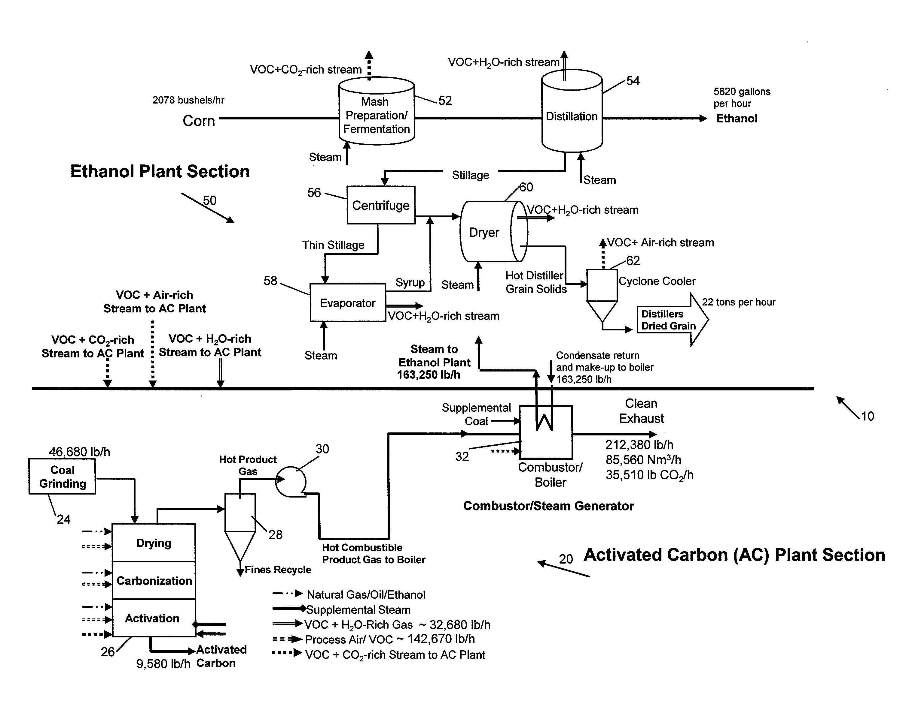
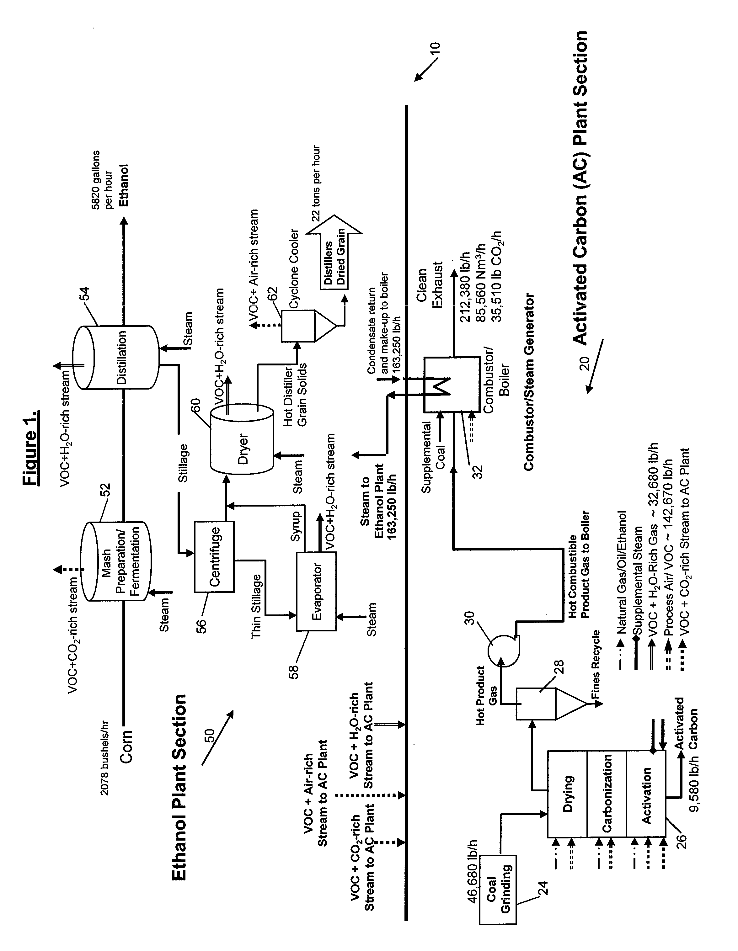
Ethanol and Activated Carbon Production Plant

[0095]An ethanol and activated carbon production plant with the identified improvements (FIG. 1) and advantages relative to stand-alone plants is described below. Coal (lignite) of the composition provided below is used as feed stock.

Compositionwt-%CCarbon34.6HHydrogen3.5SSulfur0.61OOxygen21.6NNitrogen0.66Ash7.0H2OMoisture32.0

[0096]Activated carbon yield from the activated carbon production reactor is about 20-30 percent based on wet feed input. For a 46,684 lb / hour wet lignite input, this plant yields about 9,580 lb / hour (20% yield) of activated carbon product.

[0097]A typical activated carbon composition is shown below obtained from processing the above-described feed stock in the proposed inventive method.

Compositionwt-%CCarbon68HHydrogen0.5SSulfur1.5OOxygen0.5NNitrogen0.7Ash28.0H2OMoisture1.0

[0098]Steam requirement for activation for the activated carbon production plant is about 0.7 lb of steam per pound of wet feed. For a 46,684 lb / h...

example 3

Coal-Fired Activated Carbon Plant with Flue Gas Quench

[0108]An example of a typical coal-fired activated carbon production plant is provided below. Lignite of the composition provided in the previous example is used as feed stock. Activated carbon yield is about 20 percent based on wet feed input. A portion of the heat generated from the combustion of the product gases from the reactor is used to generate process steam. Steam requirement for the activated carbon production plant is about 0.7 lb of steam per pound of wet feed. For a 46,684 lb / hour wet lignite input, this translates to about 32,680 lb / hour of steam. This plant yields about 9,580 lb / hour of activated carbon product. The remainder of the heat from the combustion of the product gas from the activated carbon production reactor has to be quenched with a water spray. About 133,380 lb / hour of water is required to quench the flue gases and achieve an outlet flue gas temperature of about 300° F., which is optimum for operation...

example 4

Coal-Fired Activated Carbon Plant with Heat Recovery for Power Generation

[0109]In a typical coal-fired activated carbon production plant flow diagram with heat recovery for power generation, lignite of the composition provided in the previous examples is used as feed stock. Activated carbon yield is about 20 percent based on wet feed input. A portion of the heat generated from the combustion of the product gases from the reactor is used to generate process steam. Steam requirement for the activated carbon production plant is about 0.7 lb of steam per pound of wet feed. For a 46,684 lb / hour wet lignite input, this translates to about 32,680 lb / hour of steam. This plant yields about 9,580 lb / hour of activated carbon product. The remainder of the heat from the combustion of the product gas from the activated carbon production reactor is cooled, while additional steam is generated. This steam is sent to a steam turbine for electricity production. About 10 MWe of electricity can be expec...


PUM

PropertyMeasurementUnit
surface areaaaaaaaaaaa
temperaturesaaaaaaaaaa

Abstract

A method in which a parent hydrocarbon-rich material is processed so as to produce both a carbon-rich solid material that has a higher carbon to hydrogen ratio than that of the parent material and a carbon-deficient combustible gas that has a lower carbon to hydrogen ratio than the parent material. In the process, the material is activated by exposing it to a hot gas stream having elevated levels of one or both of carbon dioxide and water vapor. The combustible gas is combusted to produce heat. At least about 80% of the heat is used in one or more endothermic steps that include drying coal or biomass.

Description

CROSS-REFERENCE TO RELATED APPLICATIONS[0001]This application is a continuation in part of PCT / US09 / 34356 titled “Method of Manufacturing Carbon-Rich Product and Co-Products” filed on Feb. 18, 2009, which itself claimed priority of the following three provisional patent applications: 61 / 066,247 filed Feb. 19, 2008; 61 / 131,952 filed Jun. 14, 2008; 61 / 189,045 filed Aug. 16, 2008. This application also claims priority of provisional patent application Ser. No. 61 / 210,885 filed on Mar. 24, 2009. The disclosures of all of these prior applications are incorporated herein by reference.FIELD OF THE INVENTION[0002]The present invention relates generally to the production of a carbon-rich product (e.g. activated carbon) from a hydrocarbon material such as coal and / or biomass with the generation of excess energy and the generation of a co-product which utilizes the excess energy for its production.BACKGROUND OF THE INVENTION[0003]Many industrial processes require energy for one or more process...

Claims


Application Information

Patent Timeline
Patent Type & Authority Applications(United States)
IPC IPC(8): F23C99/00C01B32/336
CPCF23K5/002C01B31/08Y02E50/17C01B31/12C04B7/36C04B11/02C10B49/02C10B53/04C10B53/08C10B57/10C12P7/06C04B2290/20C10L5/361C10L5/366C10L9/08C12M43/02C12M43/06F01K17/02C04B7/4407Y02P40/121C01B32/30C01B32/336C01B32/342C01B32/318Y02E50/10Y02P40/125C07C29/00D21H11/14
Inventor SRINIVASACHAR, SRIVATS
Owner SRINIVASACHAR SRIVATS
Why Eureka
Try Eureka