Current Diverter Ring

a current diverter and ring technology, applied in the direction of bearing assembly, dynamo-electric components, mechanical equipment, etc., can solve the problems of affecting the operation of the electric motor, the failure of the bearing and the damage of the electrical motor using variable frequency drives, and the inability to maintain the rotating equipment in a timely manner. to achieve the effect of preventing the leakage of lubrican

Inactive Publication Date: 2010-07-29
INPRO INC
View PDF20 Cites 27 Cited by
  • Summary
  • Abstract
  • Description
  • Claims
  • Application Information

AI Technical Summary

Benefits of technology

[0013]An objective of the current diverter ring is to provide an improvement to seals or bearing isolators to prevent leakage of lubricant and entry of contaminants by encompassing the stator within the rotor to create an axially directed interface at the radial extremity of the rotor. It is also an objective of the current diverter ring to disclose and claim an apparatus for rotating equipment that conducts and transmits and directs accumulated bearing current to ground.

Problems solved by technology

Adequate maintenance of rotating equipment, particularly electric motors, is difficult to obtain because of extreme equipment duty cycles, the lessening of service factors, design, and the lack of spare rotating equipment in most processing plants.
Lip seals or other contacting shaft seals often quickly wear to a state of failure and are also known to permit excessive amounts of moisture and other contaminants to immigrate into the oil reservoir of the operating equipment even before failure has exposed the interface between the rotor and the stator to the contaminants or lubricants at the radial extremity of the seal.
The problems of bearing failure and damage as applied to electrical motors using variable frequency drives (VFDs) is compounded because of the very nature of the control of electricity connected to VFD controlled motors.
There are many causes of bearing current including voltage pulse overshoot in the VFD, non-symmetry of the motor's magnetic circuit, supply unbalances, transient conditions, and others.
This random and frequent discharging has an electric discharge machining (EDM) effect, which causes pitting of the bearing's rolling elements and raceways.
Eventually, the deterioration will lead to complete bearing failure.3 3See www.Greenheck.com
Most external applications add to costs, complexity, and exposure to external environmental factors.
However, installing insulated bearings does not eliminate the shaft voltage, which will continue to find the lowest impedance path to ground.
Thus, insulated bearings are not effective if the impedance path is through the driven load.
Therefore, the prior art does not teach an internal, low-wearing method or apparatus to efficaciously ground shaft voltage and avoid electric discharge machining of bearings leading to premature bearing failure.

Method used


Image

  • Current Diverter Ring
  • Current Diverter Ring
  • Current Diverter Ring

Examples


Embodiment Construction

—ELEMENT LISTING

[0041]

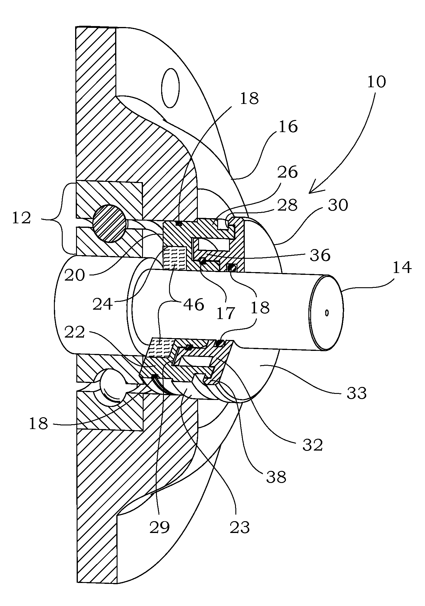
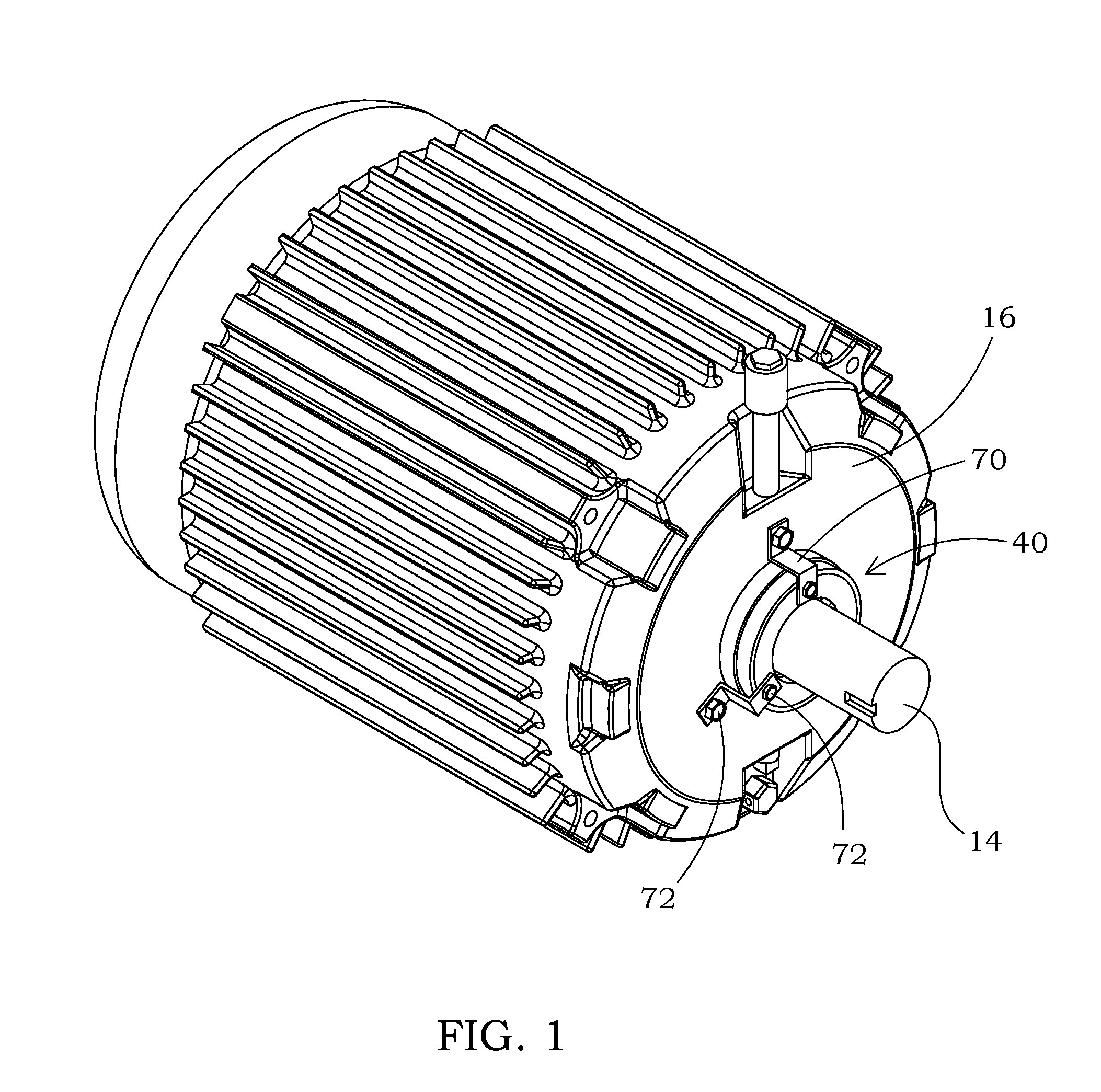
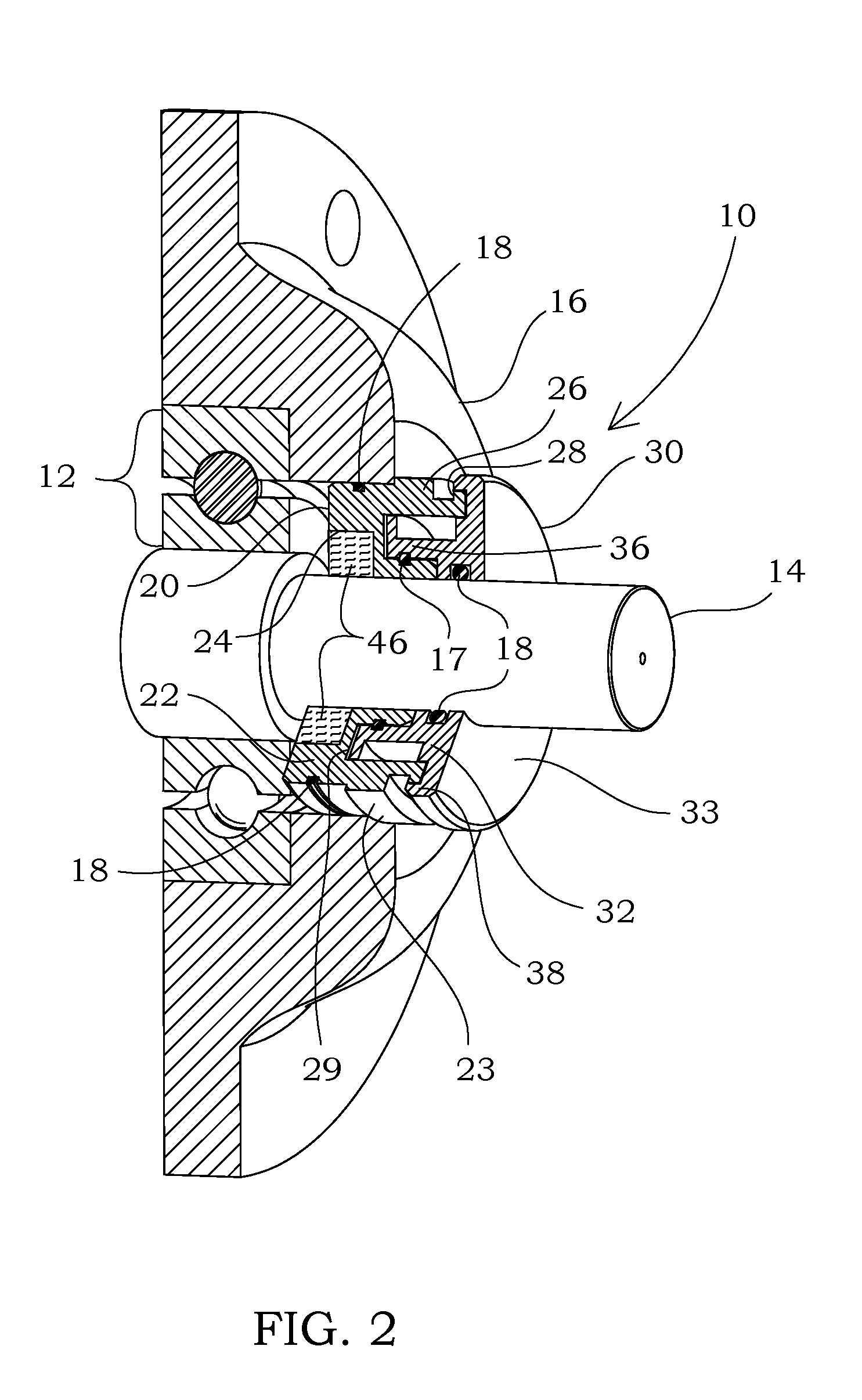
DescriptionElement No.Bearing isolator10Bearing12Shaft14Motor housing16Sealing member17O-ring18Stator20Stator main body22Stator radial exterior surface23Receptor groove24Conductive segment annular channel25Stator axial projection26Stator radial projection28Stator axial groove29Rotor30Rotor main body32Rotor axial exterior surface33First axial interface gap34aFirst radial interface gap34bRotor axial projection36Rotor radial projection38Rotor axial groove39Current diverter ring ™ (CDR ®)40CDR body41Annular channel42First wall43Second wall44CDR radial exterior surface45Conductive segment46CDR main aperture48Inner body50Radial channel52Catch52aMounting aperture54Ridge (locking)56Inner body main aperture58Outer body60Base62Annular groove64First annular shoulder65aSecond annular shoulder65bRadial projection66Outer body main aperture68Strap70Fastener72

DETAILED DESCRIPTION

[0042]Before the various embodiments of the present invention are explained in detail, it is to be ...


PUM


Abstract

The current diverter rings and bearing isolators serve to dissipate an electrical charge from a rotating piece of equipment to ground, such as from a motor shaft to a motor housing. The current diverter ring includes a body and a first and second wall protruding therefrom, which walls form an annular channel. The body may be affixed to a shaft, a motor housing, a bearing isolator, or other structure. In a first embodiment, a plurality of conductive segments is fixedly positioned within the annular channel to conduct electrical charges from the shaft to the motor housing. In a second embodiment, conductive segments are positioned between an inner and an outer body. The bearing isolator may incorporate an annular channel for retention of conductive segments within the stator of the bearing isolator or it may be fashioned with a receptor groove into which a current diverter ring may be mounted.

Description

CROSS-REFERENCE TO RELATED APPLICATIONS[0001]The present application claims priority from provisional U.S. Pat. App. Nos. 61 / 167,928 filed on Apr. 9, 2009 and 61 / 218,912 filed on Jun. 19, 2009, and also claims priority from and is a continuation-in-part of U.S. patent application Ser. No. 12 / 401,331 filed on Mar. 10, 2009, which patent application was a continuation of and claimed priority from U.S. patent Ser. No. 11 / 378,208 filed on Mar. 17, 2006, which claimed the benefit of provisional U.S. Pat. App. No. 60 / 693,548 filed on Jun. 25, 2005, all of which are incorporated by reference herein in their entireties.FIELD OF THE INVENTION[0002]The present invention relates to an electrical charge dissipating device, and more particularly to a current diverter ring™ for directing electrostatic charge to ground, which electrostatic charge is created through the use of rotating equipment.STATEMENT REGARDING FEDERALLY SPONSORED RESEARCH OR DEVELOPMENT[0003]No federal funds were used to devel...

Claims


Application Information

Patent Timeline
Patent Type & Authority Applications(United States)
IPC IPC(8): H01R39/12
CPCH01R39/64H02K11/0089H02K5/1732F16C41/002F16C2380/26H02K11/40
Inventor ORLOWSKI, DAVID C.HOEHLE, NEIL F.TEJANO, ROBERT A.HORTON, SHAWN
Owner INPRO INC
Why Eureka
Try Eureka