Macroporous carbon nanofoam composites and methods of making the same

a technology composites, which is applied in the field of macroroporous carbon nanofoam composites and methods of making the same, can solve the problems of incomplete volume filling of interfiber voids, high cost of templating approaches, and rf coatings on individual fibers, so as to reduce the hydrophobicity of carbon fibers and enhance the uniform uptake of fluid. , the effect of reducing the hydrophobicity

Inactive Publication Date: 2010-07-29
UNITED STATES OF AMERICA
View PDF7 Cites 16 Cited by
  • Summary
  • Abstract
  • Description
  • Claims
  • Application Information

AI Technical Summary

Benefits of technology

[0017]A method is disclosed to fabricate carbon foams comprising a bicontinuous network of disordered or irregular macropores that are three-dimensionally interconnected via nanoscopic carbon walls. The method accounts for (1) the importance of wetting (i.e., matching the surface energies of fiber to sol) and (2) the viscosity of the microheterogeneous fluid filling the voids in the carbon paper. Nonpolar, nonaqueous precursor fluids can be directly infiltrated into the carbon paper. For processing with aqueous-based precursor fluids or polar organic-based precursor fluids, or mixed aqueous/polar organic-based precursor fluids, carbon fiber papers are mildly oxidized by plasma etching, which greatly enhances the uniform uptake of the fluid, for instance, aqueous resorcinol-formaldehyde (RF) monomer solutions are readily imbibed by carbon paper after mild oxygenation of the fiber surfaces because the treatment diminishes the hydrophobicity of the carbon fibers. The RF solutions are oligomerized prior to infiltration and are cured into con

Problems solved by technology

Most RF/carbon fiber composites have used as-received fiber papers without chemical modifications to the fiber surfaces thereby yielding dense RF coatings on individual fibers and incomplete volume filling of the interfiber voids.
However, templating approaches require extensive synthetic and time costs.
Unsupported carbon aerogel films and monoliths can achieve pore sizes within a similar size regime as carbon nanofoams, but their low densities and the absence of an underlying fiber paper array impede electronic conduction.
Carbon aerogels are also less flexible than fiber-supported nanofoams, which impairs their use in electrode structures relevant for device applications.
The brittle mechanical character and modest electronic conductivity of carbon aerogel monoliths (˜1 S cm−1) typically necessitates pulverizing the architecture and forming composite structures with conductive additives and polymer binders.
Most RF/carbon fiber composites, however, ha

Method used


Image

  • Macroporous carbon nanofoam composites and methods of making the same
  • Macroporous carbon nanofoam composites and methods of making the same
  • Macroporous carbon nanofoam composites and methods of making the same

Examples


example 1

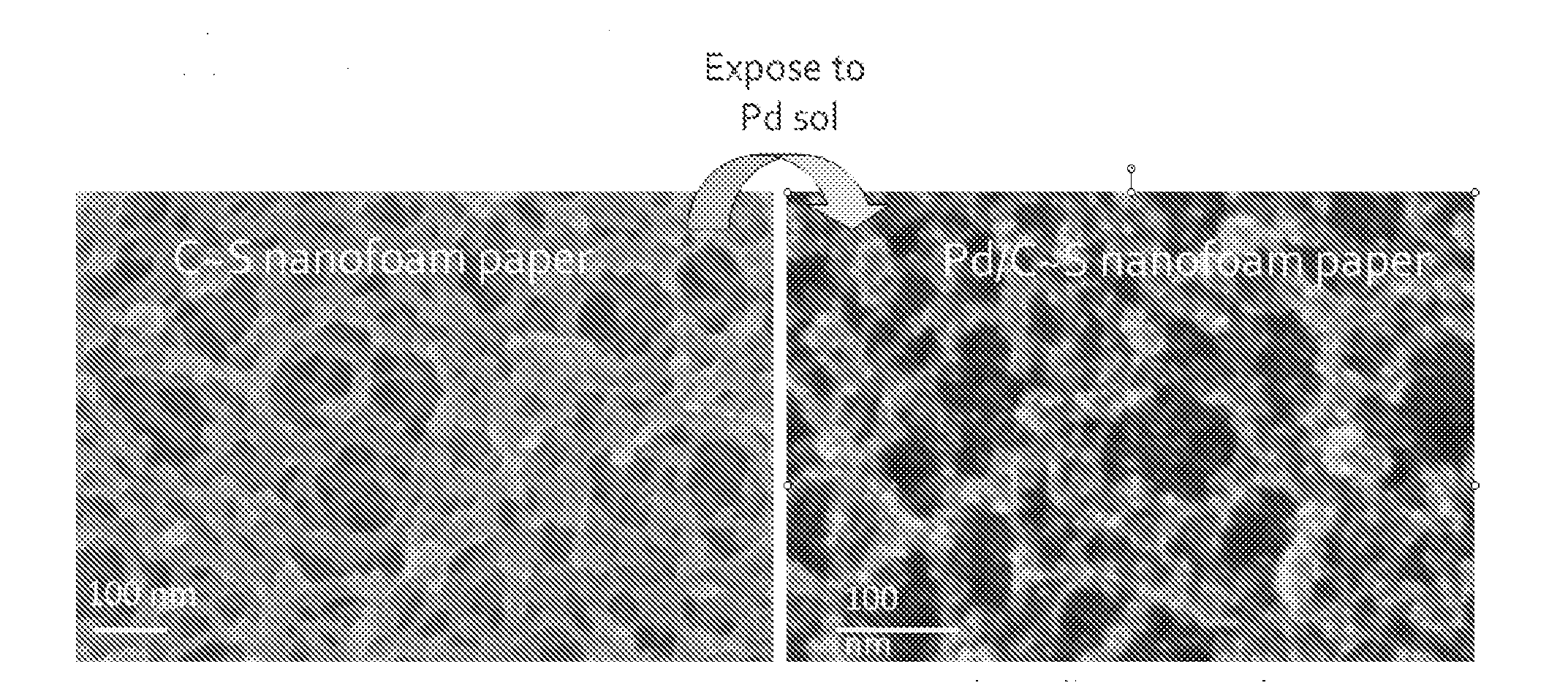
[0058]Low-density RF polymers are deposited on carbon fiber papers by the following technique. All samples were prepared from a resorcinol-to-formaldehyde (R / F) ratio of 1:2 and a R / C ratio of at least 1500:1 All reagents were purchased from Aldrich, and were used without further purification. Glass microscope slides purchased from Fisher Chemicals were cut to 2.75 cm×2.5 cm dimensions and degreased with acetone. Toray carbon fiber papers (TGP-050, density ˜0.4 g cm−3, 110-μm thick) and Lydall Technimat® carbon fiber papers (6100-050, density ˜0.2 g cm−3, 384-μm thick) were cut in 2.5 cm×1.5 cm strips and plasma etched (30 W) in the presence of moist air (0.4-0.8 ton) for 30 min. Carbon fiber paper is hydrophobic because of its nonpolar carbon bonds; plasma etching oxidizes the carbon fiber surfaces and permits the aqueous RF solution to fully infiltrate the paper. The presence of water vapor during plasma etching further increases the hydrophilic properties of the fiber paper.

[0059...

example 2

[0071]Carbon nanofoams with pore sizes in the 10-50-nm range were prepared using the method previously described. 20 g of resorcinol, 29.4 g of formaldehyde, 12.3 g of H2O, 0.0384 g of Na2CO3 were combined and stirred for 30 minutes. The resulting mixture was allowed to stand at room temperature for 2.5 hours. The resulting RF sol was then infiltrated into the carbon fiber-paper, in accordance with the method of Example 1 and 2. The RF-impregnated papers were then packaged and placed in a table-top pressure cooker at 90° C. for at least 9 h to form the RF-polymer nanofoam paper having pore sizes in the range of from about 10 nm to about 50 nm.

example 3

[0072]Carbon nanofoams with pore sizes in the range of 500 to 1000 nm were prepared using the method previously described in Examples 1 and 2. Resorcinol (7.0932 g), 10.4842 g of formaldehyde (37%), 9.8589 g of H2O, and 0.0045 g of sodium carbonate were stirred together for about 30 min. The resulting solution was allowed to stand at room temperature for about 5 h. The resorcinol-formaldehyde (RF) sol was then infiltrated into carbon fiber-paper by the method described in Example 1. The resulting RF-nanofoam papers were allowed to sit at room temperature for 6 days. The RF-nanofoam papers were then heated at 90° C. in a table-top pressure cooker for 12 h to form the final RF-nanofoam paper.

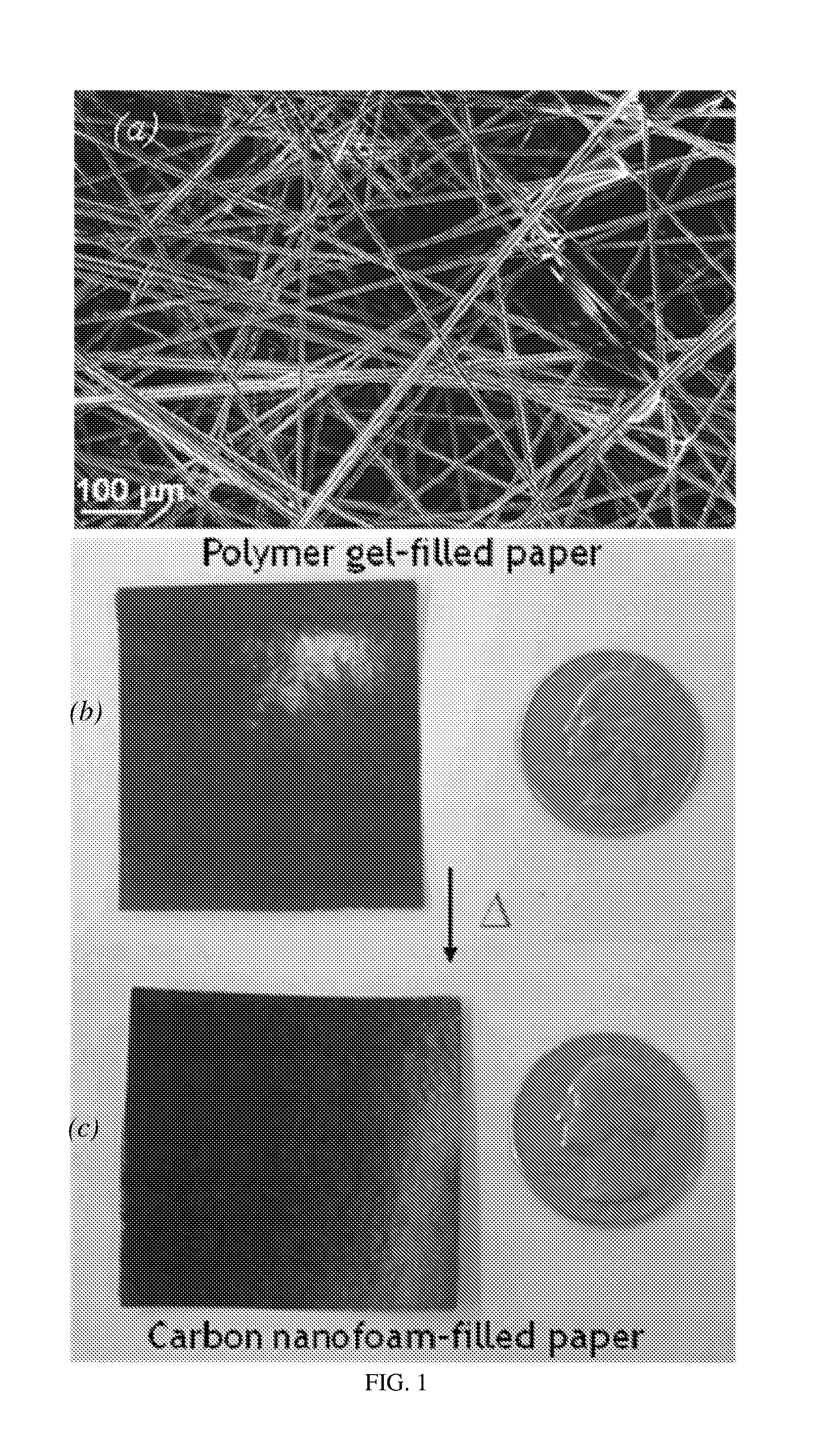
[0073]FIG. 1 shows (a) scanning electron micrograph of 0.2 g cm−3 carbon fiber paper (Lydall Filtration / Separation, Inc.). Photographs of carbon-fiber-supported RF foam before (b) and after (c) pyrolysis at 1000° C. in flowing argon to form carbon-fiber-supported carbon nanofoam. Note that the shi...


PUM

PropertyMeasurementUnit
Temperatureaaaaaaaaaa
Fractionaaaaaaaaaa
Fractionaaaaaaaaaa

Abstract

A method is disclosed to fabricate carbon foams comprising a bicontinuous network of disordered or irregular macropores that are three-dimensionally interconnected via nanoscopic carbon walls. The method accounts for (1) the importance of wetting (i.e., matching the surface energies of fiber to sol) and (2) the viscosity of the microheterogeneous fluid filling the voids in the carbon paper. Carbon fiber papers are mildly oxidized by plasma etching, which greatly enhances the uniform uptake of resorcinol-formaldehyde (RF) mixtures. The RF solutions are oligomerized prior to infiltration and are cured into continuous polymeric webs that hang supported between adjacent carbon fibers; the polymer-fiber composites are pyrolyzed and retain a sponge-like morphology with 10-1000-nm pores and integrated electronic pathways

Description

CROSS-REFERENCE TO RELATED APPLICATIONS[0001]This Application claims the benefit of U.S. Provisional Application 61 / 115,250 filed on Nov. 17, 2008, hereby incorporated herein in its entirety.STATEMENT REGARDING FEDERALLY SPONSORED RESEARCH OR DEVELOPMENT[0002]Not applicable.REFERENCE TO A COMPACT DISK APPENDIX[0003]Not applicable.BACKGROUND OF THE INVENTION[0004]Carbon foams with macroscopic porosities have been previously reported, but advanced carbon nanoarchitectures have since been fabricated as ultraporous electrodes for miniaturized energy storage devices (see R. W. Pekala, et al., J. Non-Cryst. Solids, 225, 74 (1998); E. Frackowiak et al., Carbon, 39, 937 (2001); M. Glora, et al., J. Non-Cryst. Solids, 285, 283 (2001), A. E. Fischer et al., ECS Transactions, 3, 61 (2007) and A. E. Fischer, et al., Nano Lett., 7, 281 (2007)) rapid chemical sensors (see C. Z. Lai, et al., Anal. Chem., 79, 4621 (2007)), and efficient separations media (see S. Villar-Rodil, et al., Chem. Mater., ...

Claims


Application Information

Patent Timeline
IPC IPC(8): B32B3/26B05D3/02
CPCC04B35/52C04B35/83C04B38/0032C04B2111/00844C04B2235/422H01B1/04C04B2235/5248C04B2235/48C04B38/0054Y10T428/249978Y10T428/249921
Inventor LYTLE, JUSTIN C.LONG, JEFFREY W.BARROW, AMANDA JUNESAUNDERS, MATTHEW PAULROLISON, DEBRA R.DYSART, JENNIFER L.
Owner UNITED STATES OF AMERICA
Why Eureka
Try Eureka