Systems and Methods for Surface Modification by Filtered Cathodic Vacuum Arc

a vacuum arc and filtering cathode technology, applied in the field of system and method for surface modification by filtering cathode vacuum arc, can solve the problem of a-c overcoat space being a major obstacl

Inactive Publication Date: 2010-07-29
NAT UNIV OF SINGAPORE +1
View PDF10 Cites 82 Cited by
  • Summary
  • Abstract
  • Description
  • Claims
  • Application Information

AI Technical Summary

Benefits of technology

[0004]Provided are filtered cathodic vacuum arc systems useful for modifying a surface of a substrate (e.g. depositing a thin film of a material onto a surface of a substrate and/or implanting a material into the near-surface region of a substrate). The systems are configured to stabilize a dc arc discharge plasma from an arc source. Also provided are methods for modifying a surface of a substrate, which in some cases includes

Problems solved by technology

The space occupied by the a-C overcoat is a major obstacle in achievi

Method used


Image

  • Systems and Methods for Surface Modification by Filtered Cathodic Vacuum Arc
  • Systems and Methods for Surface Modification by Filtered Cathodic Vacuum Arc
  • Systems and Methods for Surface Modification by Filtered Cathodic Vacuum Arc

Examples


example 1

FCVA on Silicon Substrates

I. Introduction

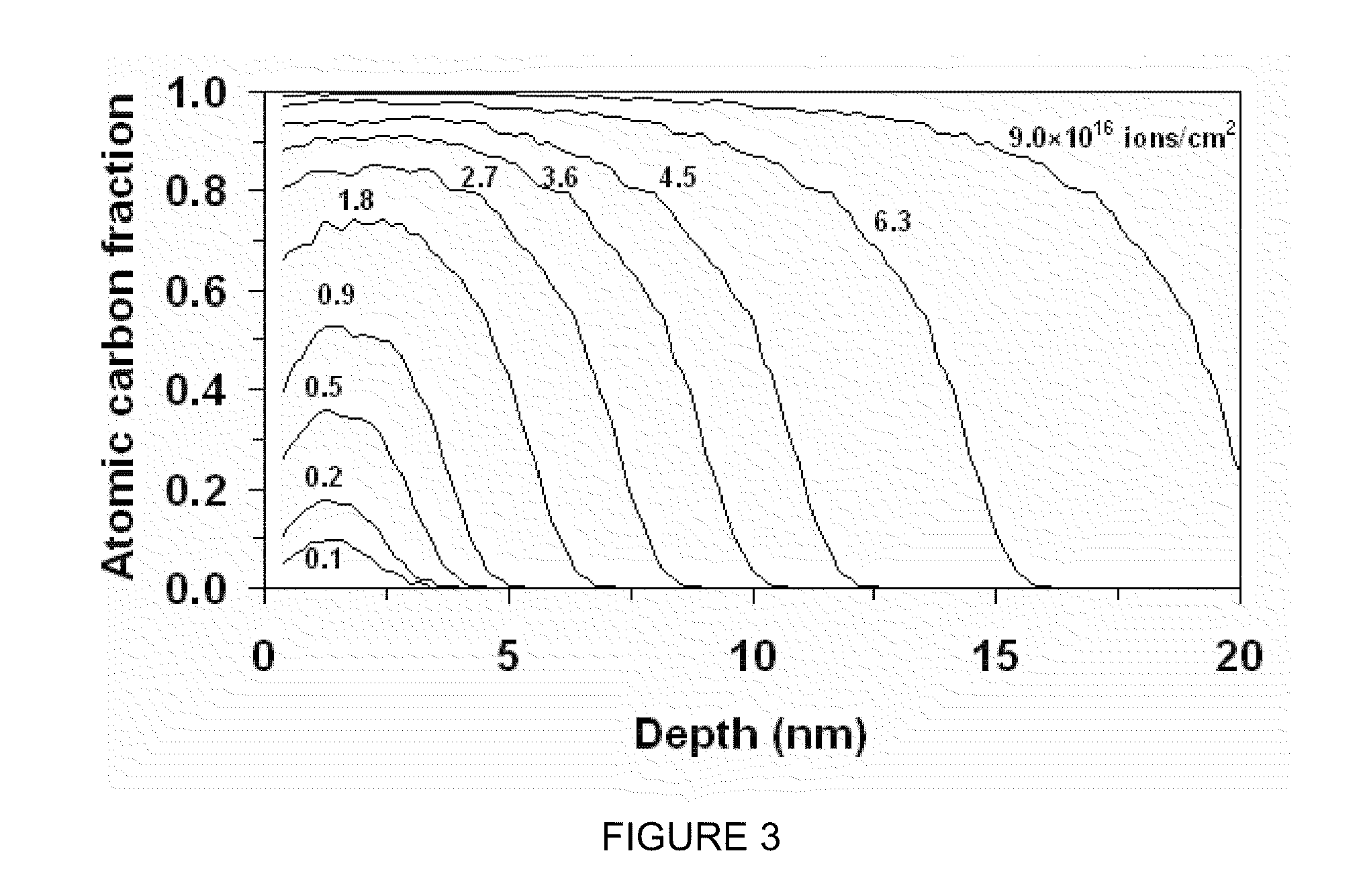
[0084]Filtered cathodic vacuum arc (FCVA) deposition and the properties of thin films synthesized by FCVA were studied. FCVA was studied by holding the process time, which is linearly related to the ion fluence, constant and adjusting the substrate bias. X-ray photoelectron spectroscopy (XPS) was used to examine carbon bonding changes in terms of implanting ion fluence and substrate bias. Film thickness and composition depth profiles were determined from T-DYN simulations and X-ray reflectivity (XRR) measurements. The film roughness, measured with an atomic force microscope (AFM), was analyzed in terms of atomic carbon bonding and carbon atom diffusion at the film surface. The nanomechanical properties of the films were detected with a surface force microscope (SFM).

II. Experimental Procedures

[0085]A. Synthesis of carbon films by FCVA

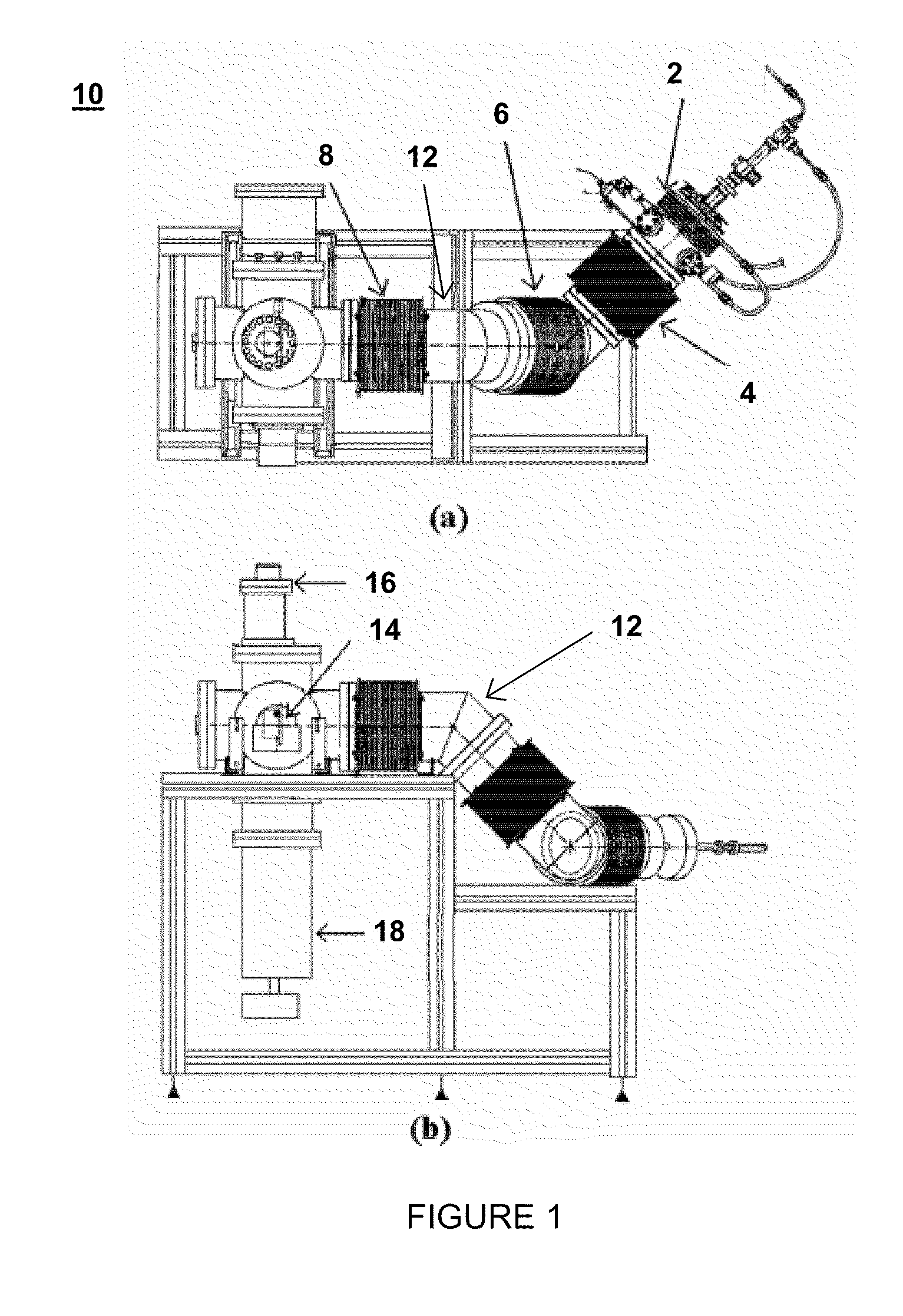
[0086]Synthesis of carbon films on Si(100) substrates was performed with a direct current (dc) FCVA system by ...

example 2

FCVA on a Magnetic Recording Medium

I. Introduction

[0105]Surface modification of the magnetic recording medium of hard disks by FCVA treatment was examined. The magnetic storage layer was exposed by sputter etching the overlying carbon overcoat. Sputter etching was performed in a high-vacuum atmosphere to minimize oxidation of the underlying magnetic storage layer. The exposed magnetic storage layer was subjected to energetic C+ ion bombardment under conditions of zero and −100 V pulsed (25 kHz frequency) substrate bias. The effects of FCVA treatment conditions on carbon implantation profiles, carbon atom hybridization, surface roughness, and nanomechanical properties of the surface-modified hard disk magnetic recording medium was analyzed using T-DYN, XPS, AFM, and SFM.

II. Experimental Procedures

[0106]A. Sample Preparation

[0107]Unlubricated hard disks having a diameter of 3.5 in. were cut into 10×10 mm2 samples. The magnetic storage layer was composed of 61-63 atomic % Co, 12-15 ato...


PUM

PropertyMeasurementUnit
Thicknessaaaaaaaaaa
Magnetic fieldaaaaaaaaaa

Abstract

Provided are filtered cathodic vacuum arc systems useful for modifying a surface of a substrate (e.g. depositing a thin film of a material onto a surface of a substrate and/or implanting a material into the near-surface region of a substrate). The systems are configured to stabilize a do arc discharge plasma from an arc source. Also provided are methods for modifying a surface of a substrate, which in some cases includes depositing a material onto a surface of a substrate, in some cases includes implanting a material into the near-surface region of a substrate, and in some cases includes both depositing a material onto a surface of a substrate and implanting a material into the near-surface region of a substrate using the subject cathodic arc systems. In addition, magnetic recording media produced by the subject systems and methods are provided.

Description

CROSS-REFERENCE TO RELATED APPLICATION[0001]Pursuant to 35 U.S.C. §119(e), this application claims priority to the filing date of U.S. Provisional Patent Application Ser. No. 61 / 147,697, filed Jan. 27, 2009, which application is incorporated herein by reference in its entirety.INTRODUCTION[0002]Fabrication of magnetic recording media, such as hard disks and magnetic recording heads, includes an outermost protective layer, typically an amorphous carbon (a-C) film, deposited onto the magnetic layer of the hard disk (or directly onto a ceramic magnetic recording head) before applying a molecularly thin lubricant layer by a spin-coating method. In view of continuing demands for even higher magnetic recording densities (e.g., 10 Tbit / in2 or higher), the headspace above the media must be reduced. The space occupied by the a-C overcoat is a major obstacle in achieving magnetic recording densities on the order of 10 Tbit / in2 or higher.[0003]One type of material deposition protocol is cathod...

Claims


Application Information

Patent Timeline
IPC IPC(8): G11B5/66C23C16/50G11B5/84
CPCC23C14/022C23C14/0605C23C14/221H01J37/3266G11B5/72G11B5/8408H01J37/32055C23C14/48C23C14/325G11B5/727
Inventor KOMVOPOULOS, KYRIAKOSZHANG, HANSHENBHATIA, CHARANJIT SINGH
Owner NAT UNIV OF SINGAPORE
Why Eureka
Try Eureka