Scanning light imager

a light imager and scanning light technology, applied in the field of scanning light imagers, can solve the problems of low contrast images on the image periphery and compromise imaging accuracy

Inactive Publication Date: 2010-08-05
HANLIN JOHN HAROLD +1
View PDF0 Cites 51 Cited by
  • Summary
  • Abstract
  • Description
  • Claims
  • Application Information

AI Technical Summary

Benefits of technology

[0093]The embodiments of this invention describe the detection of atherosclerotic plaque or cancer cells by a light probe inside a blood vessel or internal to an elongate organ. The light probe is a scanner which projects light circumferentially, approximately perpendicular to the vessel/organ surface light image and receives light with a low-angle acceptance cr

Problems solved by technology

The walls (1) of the elongate structure are only obliquely illuminated, resulting in

Method used


Image

  • Scanning light imager
  • Scanning light imager
  • Scanning light imager

Examples


first embodiment

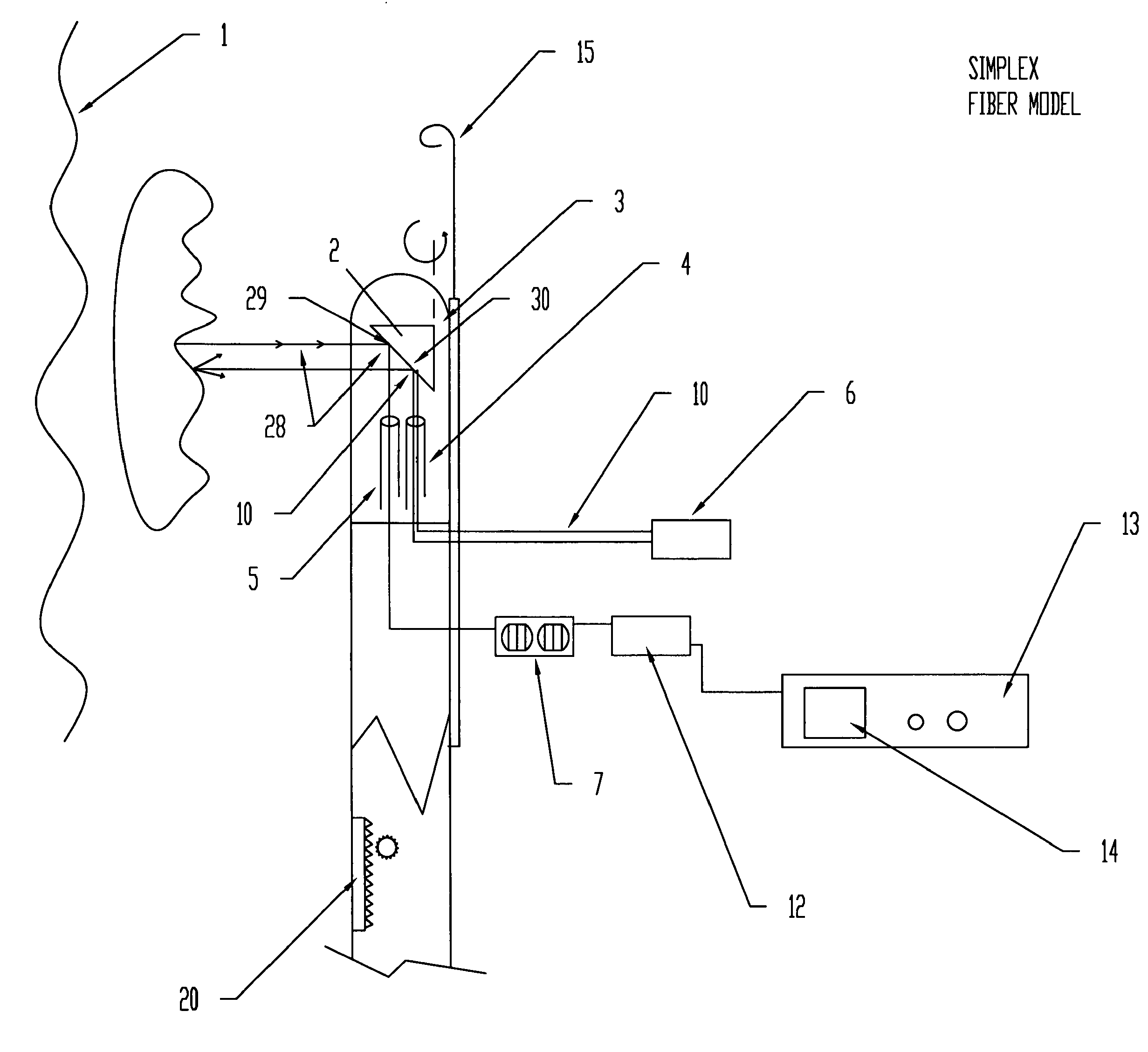
[0115]The first embodiment (FIG. 3) is a light scanning probe inserted over the wire residing in a section of interest of a coronary artery. The section of interest would generally be a region of stenosis discovered in angiography. It could also be the region occupied by a stent to evaluate stent patency and early signs of stent restenosis. If vulnerable plaque burden estimation was the goal, the first centimeter of the main coronary arteries or sections of the carotid artery would be possible locations.

[0116]The probe is composed of an outer sheath containing two flexible fiberoptic fibers, one hollow wound spring for rotation and translation of the optical assembly, and a guidewire channel permitting it to passed over an indwelling guidewire. The first embodiment consists of only two fibers: an illuminating (4) and receiving (5) fiber. The receiving fiber (5) is connected to collection optics (7) and routed to an infrared detector (12) rather than an infrared camera. The probe (3)...

second embodiment

[0145]While the first embodiment images the entire vessel wall over a 1-2 cm arterial section, the dimensions of the artery are unknown. Dimensions are required to present accurate three-dimensional images of the arterial section. Also, arterial dimensions are important in choosing the proper stent size.

[0146]Referring to FIG. 3, sizing is easily accomplished by placing a piezoelectric transducer in close proximity to the optical assembly. For example, it could be placed adjacent the optical fibers, slo pointing to the mirror / prism. At the same time an infrared light beam is directed at an arterial segment by the rotating mirror, the mirror also reflects the ultrasound signal produced by the piezoelectric transducer.

[0147]Conversely, an ultrasound transducer could direct the ultrasound 180 degrees from the infrared light (FIG. 6). As shown in FIG. 6, the piezoelectric transducer (32) is mounted on an outside face of the mirror / prism where it directs ultrasound (94) in an opposite di...

third embodiment

[0151]A multi-fiber approach demonstrates how 10 scan lines can be produced instead of one pixel spot. 10 lines was chosen as an arbitrary number for demonstration only any practical number of lines can be designed. The number of lines are limited by the fiber bundle diameter and individual fiber OD. In FIG. 7, a multi-fiber probe (92) has multiple emitting and receiving fibers (93). Ten lines of light (10) at 36 degrees apart are shown. Each line is produced by the projection of 10 receiver fibers that are adjacently located in the fiber bundle. The reflective surface of the mirror is a complex facet optical design to keep the line projection straight while the mirror is rotated. With 10 facets on the mirror each 36 degree angular section of a vessel is scanned 10 times per revolution.

[0152]With 10 scanned images of each angular section an averaging of the optical data can be accomplished with one revolution instead 10 revolutions with a single pixel detector.

[0153]The ultrasound d...


PUM


Abstract

This invention describes the detection of atherosclerotic plaque or cancer cells by a light probe inside a blood vessel or internal to an elongate organ. In one embodiment, vessel wall is imaged by employing a scanning mechanism using one emitting and one receiving fiber, whereby light is directed at a spinning mirror, approximately normal to the vessel or elongate organ surface. The light is reflected circumferentially around the vessel or elongate organ surface as the mirror rotates and received by a low-numerical aperture (NA) fiber, which transmits it to a light detector, thereby generating a set of light amplitudes circumferentially around the vessel/elongate organ surface. Multiple rings are acquired by translating the probe within the vessel/elongate organ. In another embodiment, adding a piezoelectric transducer in proximity to the distal ends of the fibers permits simultaneous ultrasound and light images to be created.

Description

FIELD OF INVENTION[0001]This invention relates to a scanning technique of light imaging of vascular wall obscured by blood and in detecting feint objects, such as cancer internally in elongate organs.REFERENCES[0002]Haney, D. Vulnerable plaque: the latest in heart disease. Assoc Press; Jan. 11, 1999 Hatsukami, T S, Ross, R, Nayak, P L, Yuan, C. Visualization of fibrous cap thickness and rupture in human atherosclerotic carotid plaque in vivo with high-resolution magnetic resonance imaging. Stroke (2000) 112: 959-964[0003]Fujimoto, J G et al. High resolution in vivo intra-arterial imaging with optical coherence tomography. Heart (1999) 82: 129-133.[0004]Chapman, Trinh, Pfieffer, Chu and Lee. Angular Domain Imaging of Objects Within Highly Scattering Media using Silicon Micromachined Collimating Arrays. IEEE Journal of Selected Topics in Quantum Electronics. (2063) V9, No 2: 257-266.[0005]Podoleanu, Review Article: Optical Coherence Tomography. British Journal of Radiology (2005) 78: ...

Claims


Application Information

Patent Timeline
IPC IPC(8): A61B6/00
CPCA61B5/0062A61B5/0066A61B5/0071A61B5/02007A61B5/0075A61B5/0086A61B5/0073
Inventor HANLIN, JOHN HAROLDAMUNDSON, DAVID CHARLES
Owner HANLIN JOHN HAROLD
Why Eureka
Try Eureka