Tunable laser module based on polymer waveguides

Inactive Publication Date: 2010-08-19
CHEM OPTICS
View PDF9 Cites 40 Cited by
  • Summary
  • Abstract
  • Description
  • Claims
  • Application Information

AI Technical Summary

Benefits of technology

[0029]The tunable laser module based on the external resonance waveguide of the present invention includes a condensing lens between the light source and the waveguide, making it possible to increase the optical coupling efficiency between the light source and the output coupler and to increase the output of the tunable laser and uses the polymer waveguide Bragg grating filter having the high thermo-optic coefficient, making it possible to generate all wavelengths within the C-band or the L-band being one of the optical communication bands using the single laser module. Also, the tunable laser module based on external resonance waveguide of the present invention uses the temperature controll

Problems solved by technology

However, the tunable filter technology is not yet grown and the tunable laser is very expensive, such that it is very difficult to develop the tunable transponder.
In the case of the tunable filter, an optical fiber Bragg grating based filter has currently developed and used; however, it has very slow tunable response time of five seconds and is very expensive, such that it is not well used in a commercial system.
Also, a light source of the tunable transponder using the DFB laser is expensive so that the transponder should have a multi-channel transponder for a backup.
As a result, the tunable transponder using the DFB laser does not provide an effective solution to reduce the stock burden of the network operators.
However, the related art using a metal heating element cannot provide a uniform operating wavelength of the filter at any time regardless of external environment since a relation between a caloric value generated in the metal heating element and the necessary operating wavelength of the filter varies according to external environment when external temperature varies.
In this case, however, the article has the problems of the metal thin film heating element for the aforementioned tunable filter operation as it is.
Since t

Method used


Image

  • Tunable laser module based on polymer waveguides
  • Tunable laser module based on polymer waveguides
  • Tunable laser module based on polymer waveguides

Examples


Example

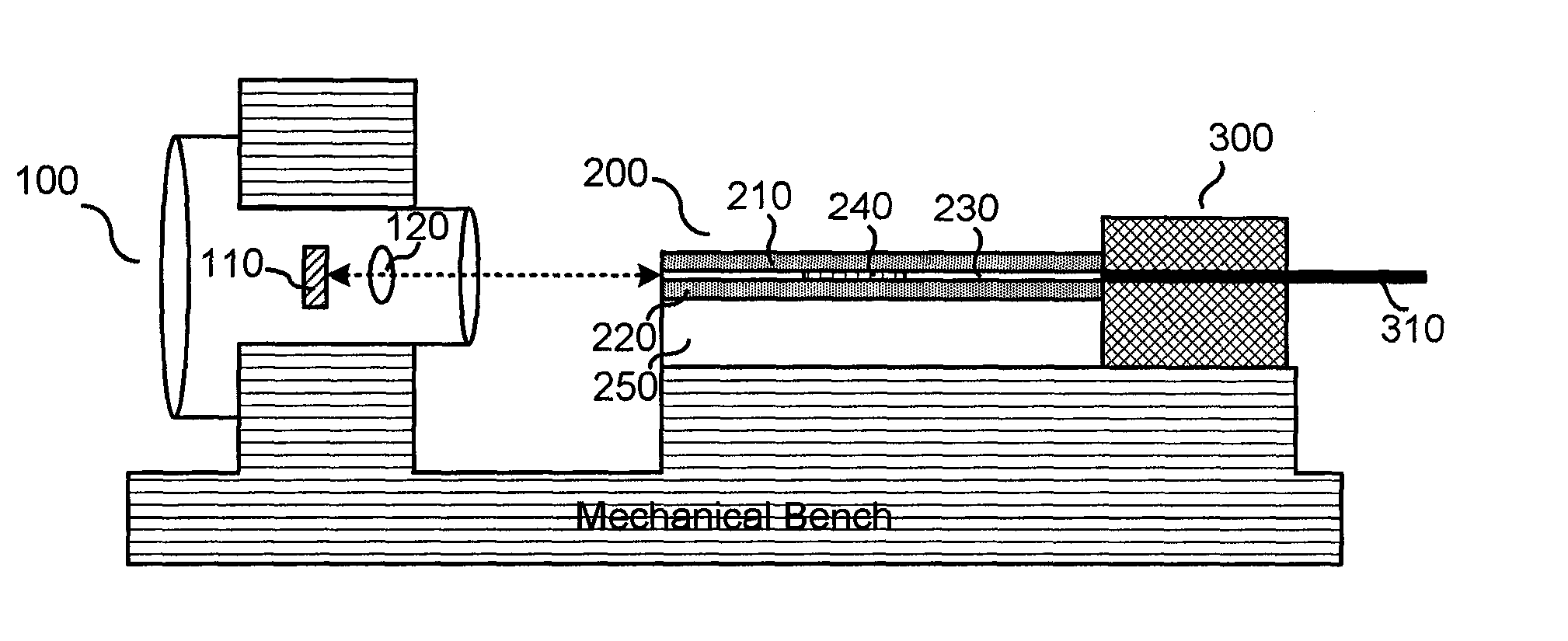
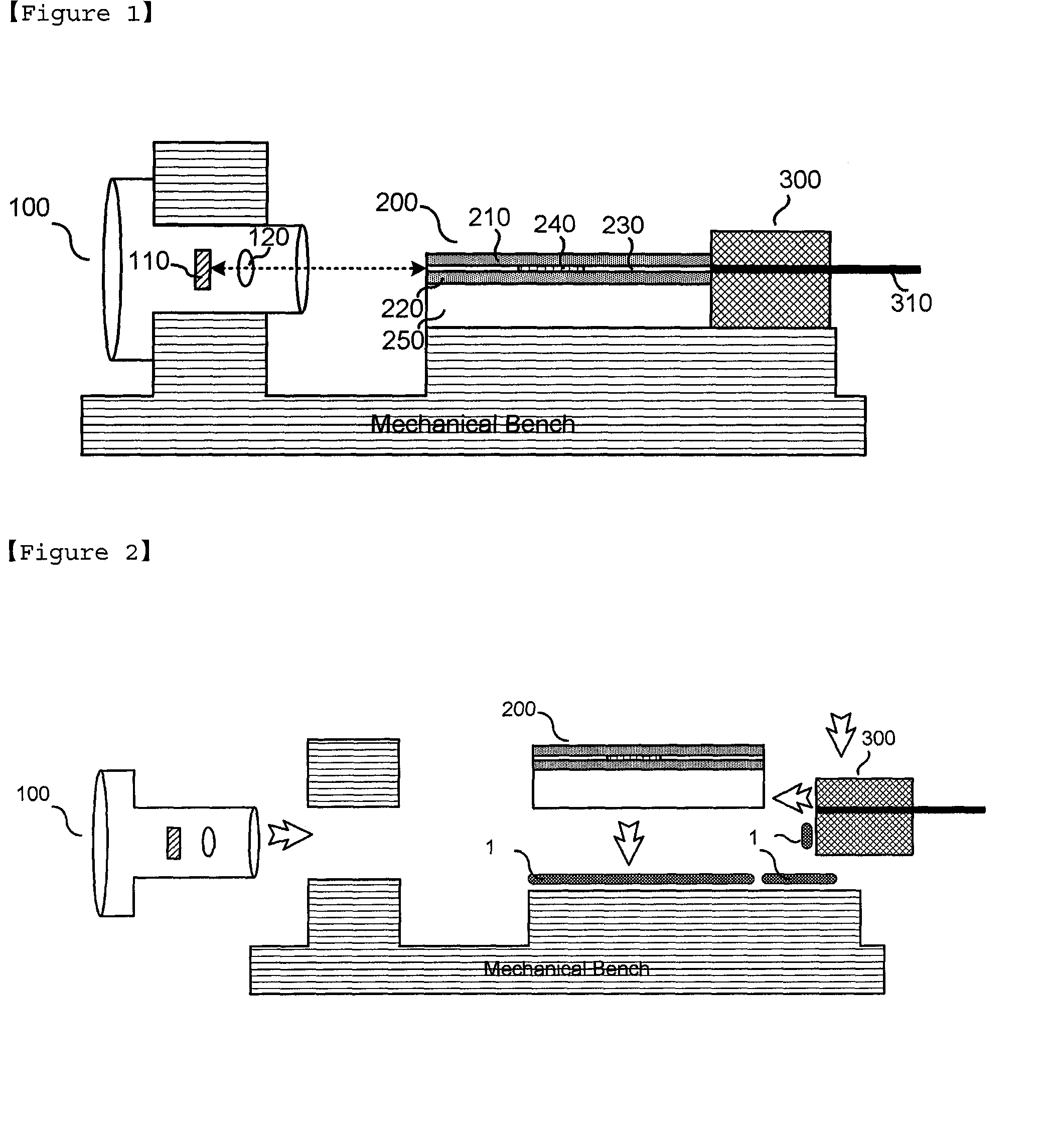
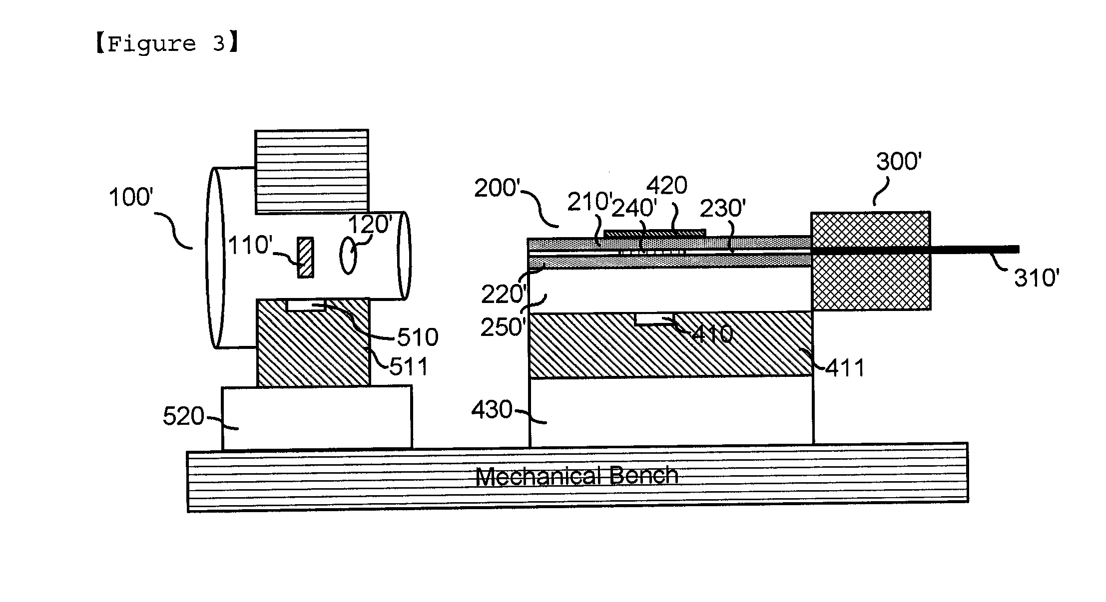
[0042]100, 100′: TO-can packaged light source[0043]110, 110′: Laser diode chip[0044]120, 120′: Optical lens[0045]200, 200′: Waveguide[0046]210, 220, 210′, 220′: Clad[0047]240, 240′: Bragg grating[0048]250: substrate[0049]300, 300′: Optical fiber supporter[0050]410, 510: Temperature sensor[0051]420: Thin film heater[0052]430: Thermoelectric cooler[0053]520: Thermoelectric cooler[0054]1: ultraviolet or thermosetting curing resin

BEST MODE

[0055]Hereinafter, a tunable laser module based on an external resonance waveguide of the present invention will be described in detail with reference to accompanying drawings. The following proposed drawings are provided as one example to sufficiently transfer to an idea of the present invention to those skilled in the art. Therefore, the present invention is not limited to the following proposed drawings and can be embodied in other forms. Also, like reference numerals throughout the specification denote like components.

[0056]At this time, technology...


PUM


Abstract

The present invention relates to a laser module based on a waveguide tunable in a broad wavelength band. More specifically, the laser module comprises: a broadband light source based on an external resonator that generates optical signals; a waveguide; at least one Bragg grating formed on the waveguide; an optical lens provided between the light source and the waveguide; a first temperature controlling device configured of a thin film heater; and a second temperature controlling device that includes a temperature sensor and a thermoelectric cooler, wherein the light output from the light source being condensed through the optical lens and input to the waveguide, and a reflecting band of the Bragg grating is controlled by a thermo-optic effect, and an oscillation wavelength is controlled by a second temperature controlling device independently of external temperature environment.

Description

TECHNICAL FIELD[0001]The present invention relates to a tunable laser module based on a polymer waveguides.BACKGROUND ART[0002]A wavelength division multiplexing (WDM) optical communication technology, which is currently applied to most backbone networks and metro networks, is a technology of transmitting a plurality of high speed signals to an optical path configured of one optical fiber by performing the wavelength division multiplexing thereon. The transmission network according to the WDM scheme essentially needs an optical add / drop multiplexer function that can selectively branch / couple some of optical wavelengths without performing photoelectric conversion and pass some of the optical wavelengths. The OADM connects between intermediate nodes existing in transmission lines in a wavelength unit, making it possible to extend the connectivity of the network and increase the efficiency of the network. An ROADM (Reconfigurable OADM) can reconfigure the branch / coupling wavelengths an...

Claims


Application Information

Patent Timeline
IPC IPC(8): H01S3/10H04B10/2581
CPCG02B6/4206G02B6/4207G02B2006/12107H01S5/146H01S5/02248H01S5/02284H01S5/141H01S5/02212H01S5/02251H01S5/02325G02B6/28H01S3/10H04B10/00H04B10/25
Inventor NOH, YOUNG-OUK
Owner CHEM OPTICS
Why Eureka
Try Eureka