Phase-locked loop circuit and an associated method

a phase-locked loop and loop circuit technology, applied in pulse manipulation, pulse technique, instruments, etc., can solve the problems of dffs, the upper limit of the operation frequency, and the loop bandwidth of the pll, so as to achieve better out-band noise suppression, limit loop bandwidth, and widen loop bandwidth

Inactive Publication Date: 2010-09-09
NAT TAIWAN UNIV
View PDF10 Cites 6 Cited by
  • Summary
  • Abstract
  • Description
  • Claims
  • Application Information

AI Technical Summary

Benefits of technology

[0016]To resolve the issues about the limited loop bandwidth of conventional PFDs, a PFD capable to handle high frequency reference signal is proposed, which can provide the PLL with a wider loop bandwidth and a better out-band noise suppression.
[0017]The first objective of the present invention is to provide a phase-locked loop (PLL) circuit to increase the frequency of a reference signal by adding a delay locked loop (DLL) and to reduce its out-band noise.

Problems solved by technology

Unfortunately, there is another constraint to the loop bandwidth of a PLL, which is the upper limit of the operation frequency of the PFD.
A drawback of such conventional tri-state PFD (2) is its operating frequency limited by the DFFs (20).
Nevertheless, the dependence on such 90 degree phase delay makes the design of DFF more complicated when the frequency of reference signal is increased, which also constrains operation frequency of PFD.

Method used


Image

  • Phase-locked loop circuit and an associated method
  • Phase-locked loop circuit and an associated method
  • Phase-locked loop circuit and an associated method

Examples


Embodiment Construction

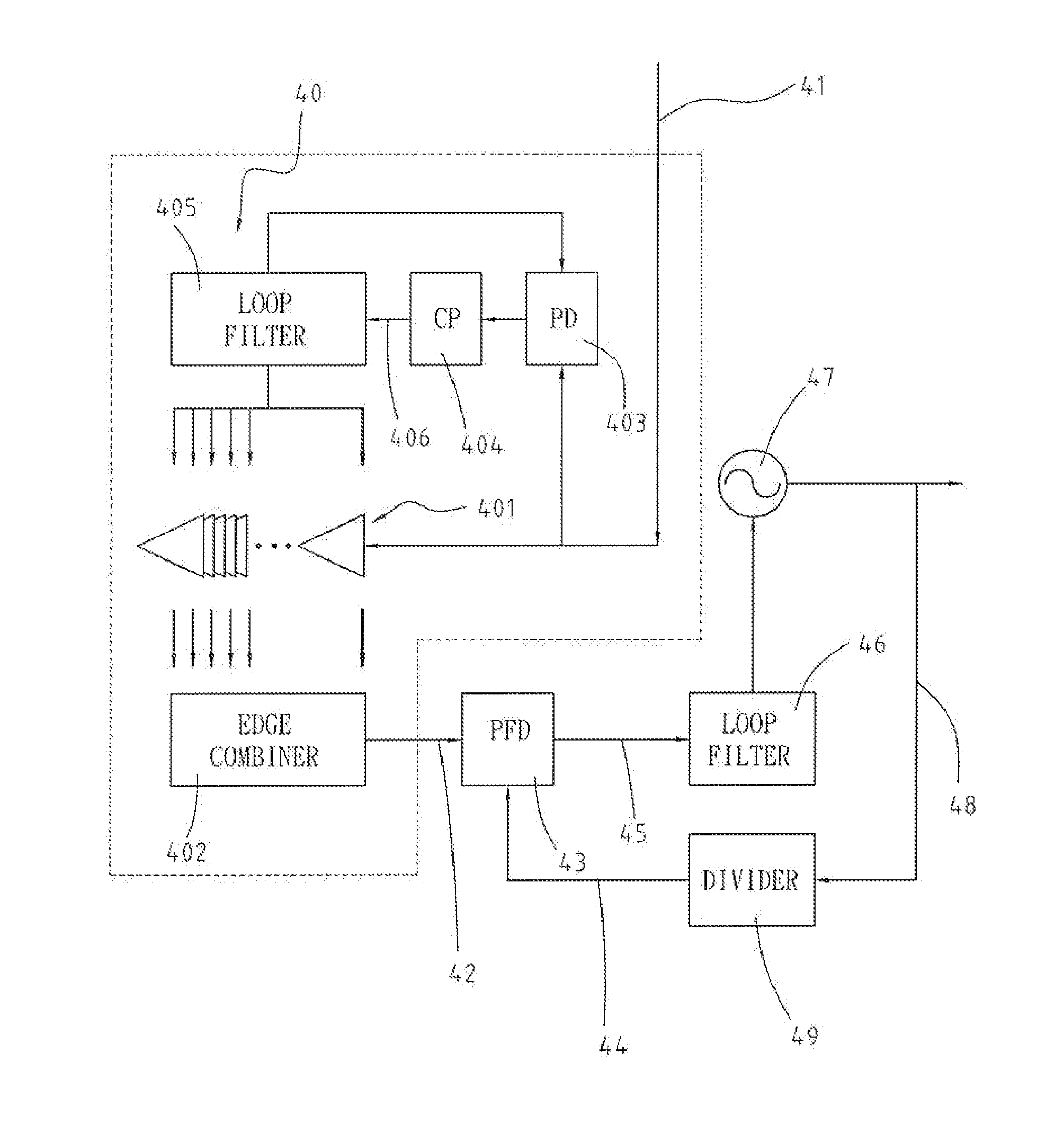
[0029]With reference to FIG. 4, a phase-locked loop (PLL) circuit in accordance with the present invention extends the loop bandwidth and suppresses the out-band noise, which comprises a delay locked loop (DLL) (40), a phase-frequency detector (PFD) (43), a loop filter (46), a voltage controlled oscillator (VCO) (47) and a frequency divider (49).

[0030]The DLL (40) receives a clock signal (41) and generates a reference signal (42) based on the clock signal (41). The reference signal (42) is a sine wave. The DLL (40) comprises multiple delay cells (401), a synchronizing phase detector (403), a synchronizing charge pump (404), a synchronizing loop filter (405) and an edge combiner (402).

[0031]The delay cells (401) receive the clock signal (41) and output a delayed clock signal (41).

[0032]The synchronizing phase detector (403) determines the synchronization of the delayed and non-delayed clock signal (41).

[0033]The synchronizing charge pump (404) is connected to the synchronizing phase ...


PUM


Abstract

The present invention relates to a PLL circuit and an associated method that allows the PLL circuit to operate at a higher operating frequency with a wider bandwidth and a better out-band noise suppression. The PLL circuit comprises a delay locked loop (DLL), a phase-frequency detector (PFD), a loop filter, a voltage controlled oscillator (VCO) and a frequency divider.

Description

FIELD OF THE INVENTION[0001]The present invention relates to a phase-locked loop circuit and an associated method. More specifically, the present invention is directed to a phase-locked loop circuit, which can operate at higher frequencies with a broader bandwidth and a better out-band noise suppression.BACKGROUND OF THE INVENTION[0002]The wavelength of a millimeter wave varies from 10 millimeters to 1 millimeter and the frequency in use may range from 30 GHz to 300 GHz. The characteristics of the millimeter waves, such as anti-interference and anti-interception, make millimeter waves preferable for high data-rate wireless communication. In the millimeter wave communication system, a phase locked loop is an important component, which generates a stable signal at for frequency conversions. By comparing the phase of the signal generated by PLL its own with the phase of another signal from an external source at low frequency, a PLL can adjust the output signal and provide a carrier wit...

Claims


Application Information

Patent Timeline
Patent Type & Authority Applications(United States)
IPC IPC(8): H03L7/06
CPCH03L7/0814H03L7/23H03L7/085H03L7/0816
Inventor LU, SHEY-SHICHEN, HSIEN-KU
Owner NAT TAIWAN UNIV
Why Eureka
Try Eureka