
Solid Phase Extraction and Ionization Device

a technology of solid phase extraction and ionization device, which is applied in the direction of instruments, nuclear engineering, transportation and packaging, etc., to achieve the effect of high sorbing capacity

Inactive Publication Date: 2010-09-30
ECOLE POLYTECHNIQUE FEDERALE DE LAUSANNE (EPFL)
View PDF18 Cites 18 Cited by
  • Summary
  • Abstract
  • Description
  • Claims
  • Application Information

AI Technical Summary

Benefits of technology

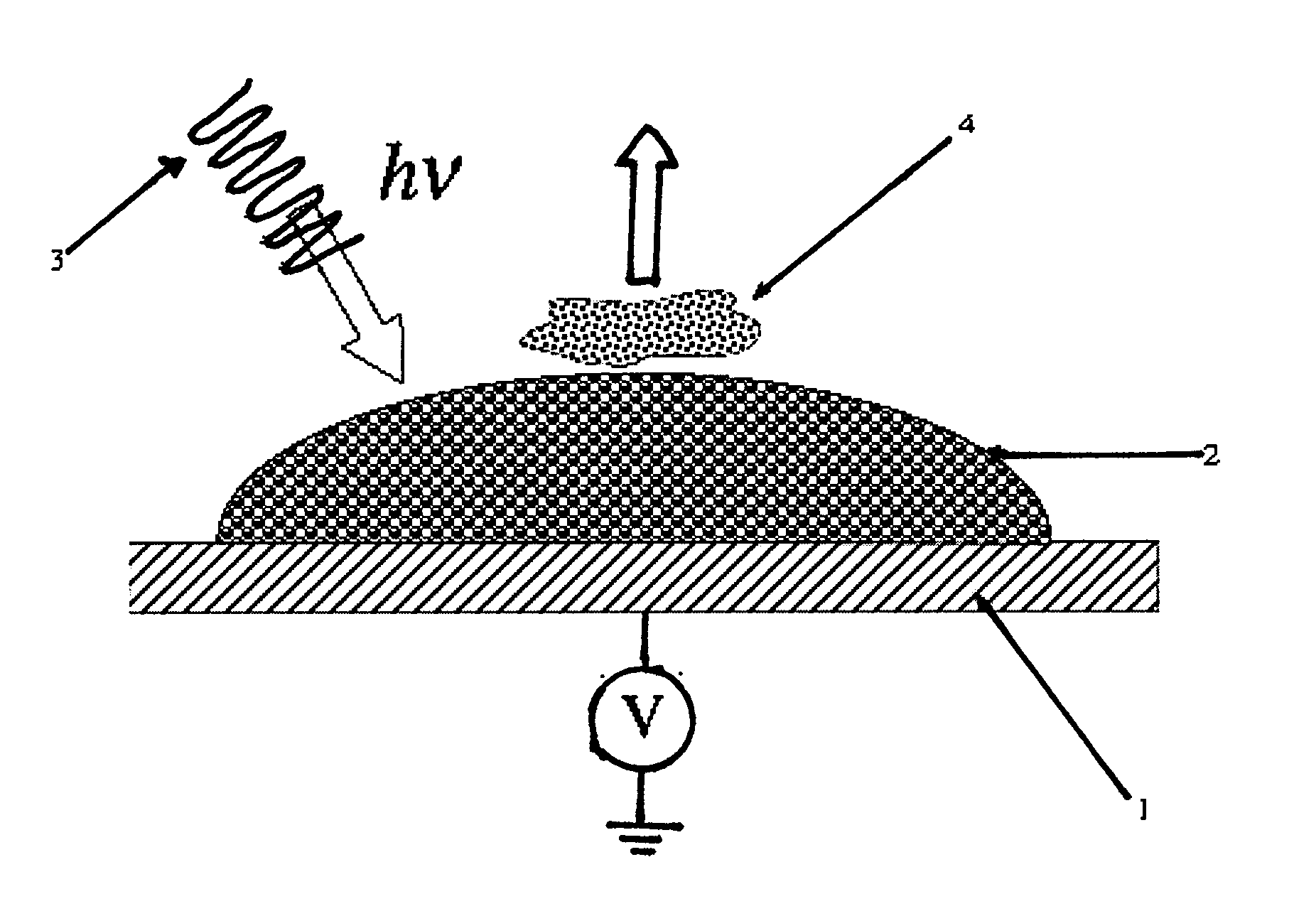
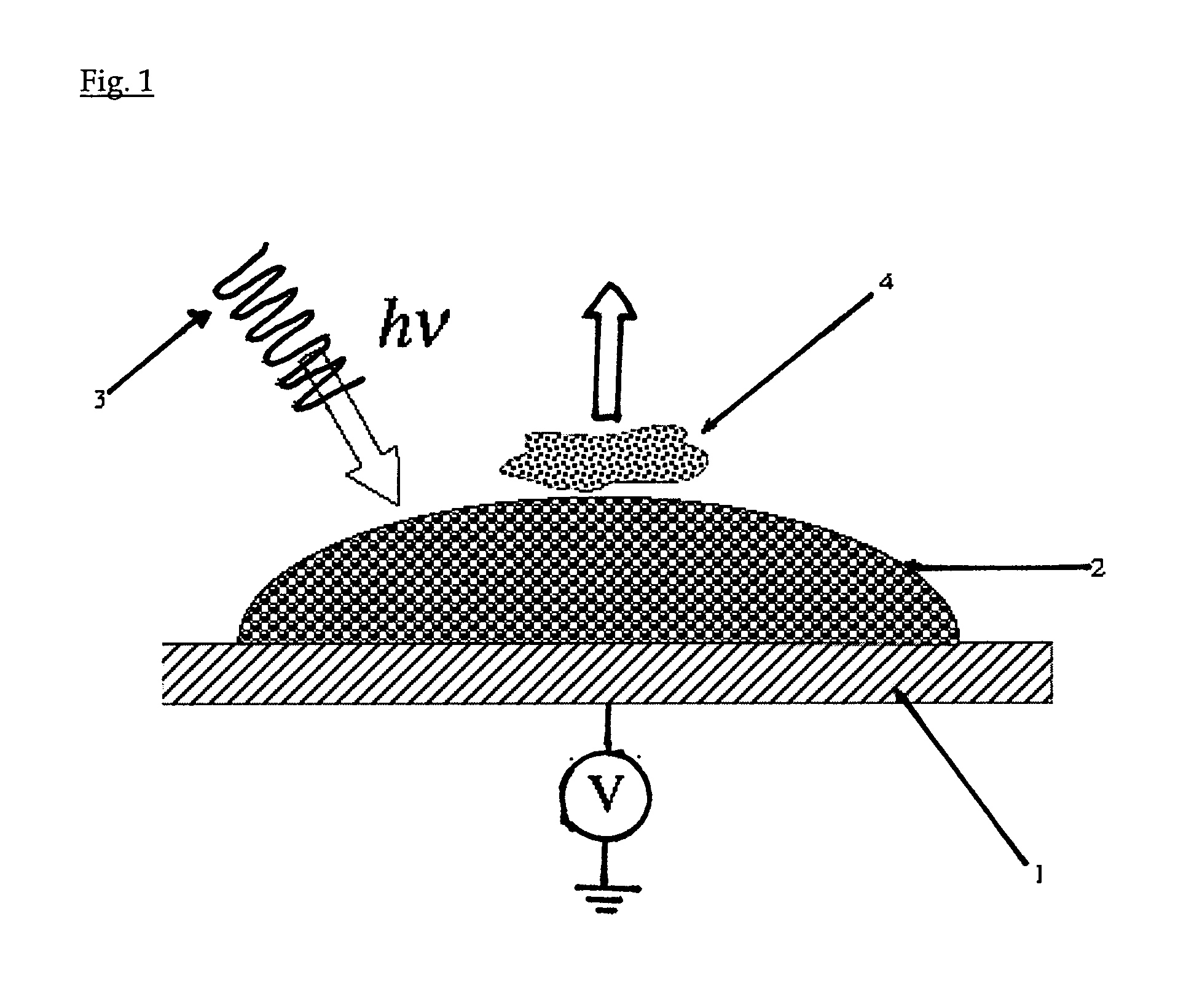
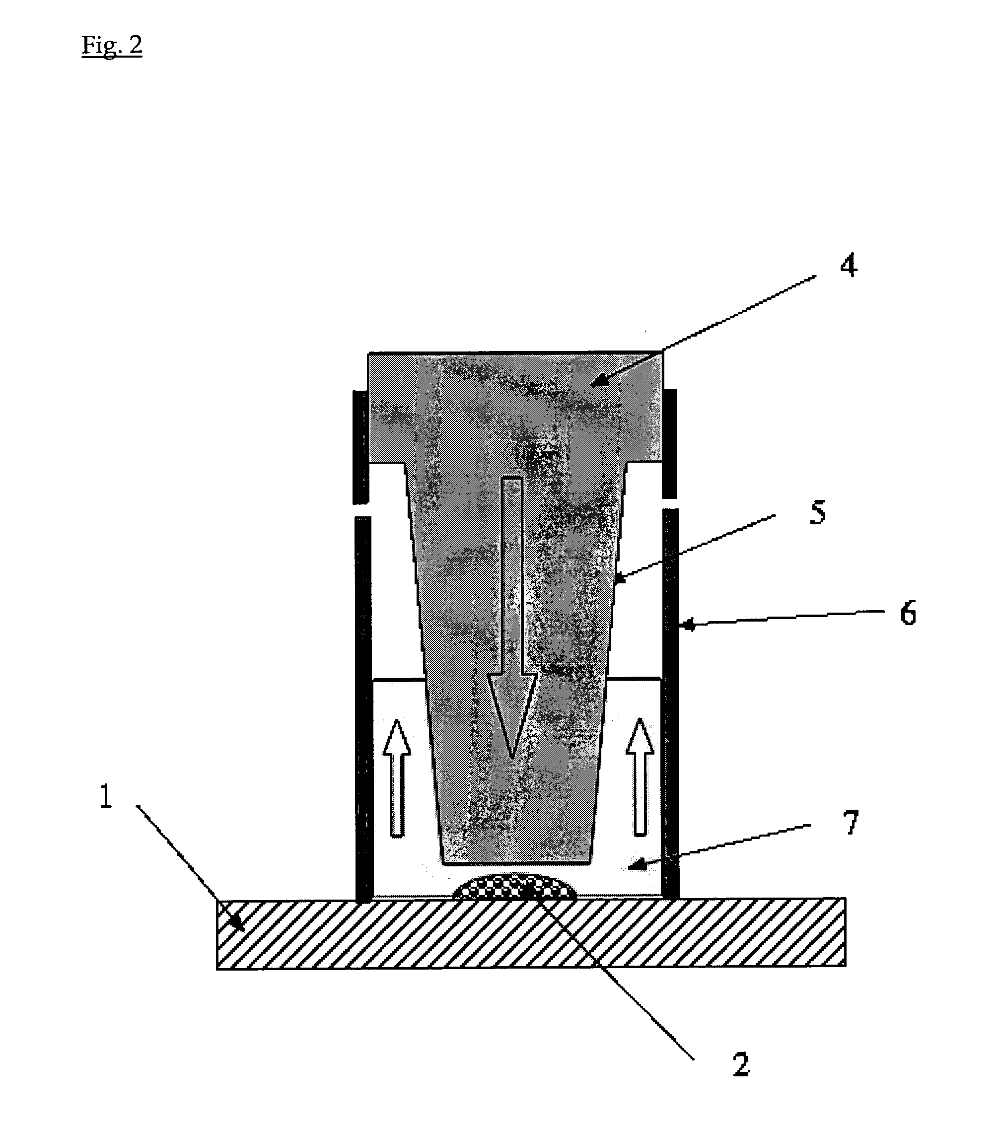
[0010]The present invention relates to LDI target plates and / or MALDI plates where a layer of sintered nanoparticles, i.e. spherical particles of which the mean radius ranges from 1 to 500 nanometers, is deposited as an array of spots on a conductive substrate, to act first as a sorbing phase for the samples. Each spot is characterized by an extremely high sorbing capacity associated to a very large specific surface area for binding a large number of molecules having a specific interaction with the nanoparticles. In this way, when a drop of sample is deposited over the spot, the latter acts as an extractor to concentrate the sample within its porous structure. Also, each spot can act as a photosensitiser either to photo-oxidize or to photo-reduce molecules, from the sample or added to the sample. In this way, the spot-inherent photoelectrochemical activity can be used for tagging reactions, disulfide bridge reductions or ion source decay reactions. After adding a crystalline acid overlayer, the plate can be used as a classical matrix assisted laser desorption ionization (MALDI) device for mass spectrometry analysis. In the absence of matrix, the spot can be used directly for laser desorption ionization (LDI) mass spectrometry. These spot covered plates provide a very efficient tool to analyze by mass spectrometry biomolecules, and in particular such molecules specifically interacting with the spot, and to study the products of the photo-induced electron transfer reactions.

Problems solved by technology

Another issue in the design of a target plate is associated to the locus of the sample of the plate.

Method used


Image

  • Solid Phase Extraction and Ionization Device
  • Solid Phase Extraction and Ionization Device
  • Solid Phase Extraction and Ionization Device

Examples


example 1

Phosphopeptide Sorption and Ionization from Sintered TiO2 Nanoparticles

TiO2 Spot Preparation

[0042]A stainless steel plate is used as a substrate. A 0.4% (0.1%-1.0%) suspension of commercially available TiO2 nanoparticles (Degussa P25) in water is prepared. Drops of the suspension are applied as a layer or an array of spots (˜2 μL) on a stainless steel plate. The drops are first allowed to dry, and then the plate is heated at 400° C. for one hour to form a spot of nanoparticles adhering to the substrate. The temperature and the duration of the sintering process depend on the nature and the size of the nanoparticles. The sintered nanoparticles are then cooled down to room temperature. The suspension can also be screen-printed directly on the metal plate.

Phosphopeptide Sorption

[0043]Peptides are obtained by protein proteolysis. Proteins, including β-casein, protein mixture of β-casein and bovine serum albumine (BSA), milk samples, are digested with trypsin in 25 mM ammonium bicarbonate...

example 2

Cysteinyl Peptide Tagging Using Photo-Oxidation of Redox Tags

[0054]The TiO2 spot preparation is similar to that of example 1.

[0055]A single cysteine-containing peptide (SSDQFRPDDCT) has been used as a model peptide. The peptide was diluted in water and kept as a stock solution. Before each experiment, aliquots were mixed respectively with DHB, MOHQ and HQ. The peptide concentration in the mixture was 5 ng / μl, i.e a concentration of 4 μM. The molar ratio peptide to redox tags was 1:1. 0.4 μL of the mixture solution was deposited on the sintered nanoparticle spots. The spot area was about 7 mm2. The sample / redox mixture was left to dry for 10 min in the dark to avoid spurious redox reactions, and then covered by an overlayer of CHCA dissolved in a solution of acetonitrile 50% / water 50% and left to dry for 5 min.

[0056]The mass spectra were obtained with an Applied Biosystems 4700 Proteomics Analyzer having a laser wavelength of 355 nm in positive reflector mode.

Oxidative Tagging Result...

example 3

Photo-Induced Peptide in-Source Decay

[0061]The TiO2 spot preparation is similar to that of example 1.

[0062]Angiotensin I and oxidized bovine insulin β-chain have been employed as model peptides. The peptides were diluted in water and kept as a stock solution with a concentration of 70 μM and 7 μM respectively. 1 μL of the solution was deposited on the sintered nanoparticle spots. The solution was left to dry for 10 min in ambient condition, and then covered by an overlayer of glucose dissolved in a solution of water (10 mg / ml) and left to dry for 5 min.

[0063]The mass spectra were obtained with a Bruker Microflex having a laser wavelength of 337 nm in both positive and negative reflector modes.

Photo-Induced Peptide in-Source Decay Results as in Example 3

[0064]In source decay is a fragmentation process occurring in the ion source rapidly after the laser shot. Being coupled with MALDI-TOF MS, it provides a useful method for sequencing peptides and proteins. Compared with the convention...


PUM

PropertyMeasurementUnit
mean radiusaaaaaaaaaa
surface areaaaaaaaaaaa

Abstract

A plate for laser desorption ionization mass spectrometry comprising an electrically conductive substrate (1) covered with an array of spots of sintered nanoparticles (2) acting as a highly efficient sorbing phase, a very sensitive photo-reactive phase and an ionization device when covered by an organic matrix or by a hole conductor or electron donor instead of an organic matrix.

Description

BACKGROUND OF THE INVENTION[0001]The present invention relates to a Laser-Desorption-Ionization (LDI) target plate where the conductive substrate is covered in defined locations by a layer of sintered nanoparticles. This adherent layer is used first as a large specific surface area solid phase on a small geometric area on the plate, therebelow called a spot, to sorb, i.e. adsorb or absorb, a sample. When molecules from the sample specifically interact with the nanoparticles, the sintered nanoparticles layer can be used as an extractor phase to concentrate these molecules on the spot. When the nanoparticles absorb light from the laser source and are photosensitized, the spot can be used as a photo-reactive phase to oxidize or reduce molecules from the sample or added to the sample. In all cases, the spot acts as a support phase for the ionization of the sorbed molecules from the sample for their analysis by mass spectrometry, for the ionization of the specifically interacting molecul...

Claims


Application Information

Patent Timeline
Patent Type & Authority Applications(United States)
IPC IPC(8): G01N24/00B05D5/12H05H1/24B01J19/08G01N30/00
CPCY10T436/24H01J49/0418
Inventor LIU, BAOHONGLIANG, QIAOLION, NIELSWAN, JINGJINGPRUDENT, MICHELROUSSEL, CHRISTOPHEYANG, PENGYUANGIRAULT, HUBERT HUGUES
Owner ECOLE POLYTECHNIQUE FEDERALE DE LAUSANNE (EPFL)
Learn More