Plasma Generation Method, Cleaning Method, and Substrate Processing Method

a technology of plasma generator and cleaning method, applied in plasma technique, hollow article cleaning, chemistry apparatus and processes, etc., can solve the problem of serious decrease in the throughput of semiconductor production, achieve significant improvement of the throughput avoid large voltage overshoot, and improve the effect of cleaning or substrate processing

Inactive Publication Date: 2010-10-07
TOKYO ELECTRON LTD
View PDF11 Cites 114 Cited by
  • Summary
  • Abstract
  • Description
  • Claims
  • Application Information

AI Technical Summary

Benefits of technology

[0082]According to the present invention, it becomes possible with a toroidal plasma generator to ignite plasma by a high-frequency power under a total pressure of 6.65-66.5 Pa while supplying a mixed gas of an Ar gas and a NF3 gas containing at least 5% of NF3 and thus it becomes possible to ignite plasma for an Ar / NF3 mixed gas. As a result, it becomes possible to eliminate the purging process of an NF3 gas from a remote plasma source, which has been necessary in single-wafer substrate processing systems whenever there is a need of turning plasma on and off, and it becomes possible to improve the throughput of cleaning or substrate processing significantly. Once the plasma has been ignited, it becomes possible to move from a ignition point of plasma to a processing point where cleaning or etching processing is conducted, without extinguishing the plasma, and efficient plasma process becomes necessary.
[0083]Further, according to the present invention, it becomes possible to ignite plasma with low voltage even in a gas containing a halogen compound, by decreasing the gas pressure at the time of plasma ignition. With this, it becomes possible to avoid occurrence of large voltage overshoot caused by large impedance change occurring at the moment of plasma ignition and associated problems of damaging in the driving power source, electrodes or coils. Further, with the present invention, it becomes possible to carry out the desired cleaning process or etching process efficiently after such ignition of plasma, by increasing the gas pressure to a predetermined process condition while sustaining plasma. Further, according to the present invention, it becomes possible to ignite plasma in the gas containing a halogen compound, and thus, the need of purging the gas containing halogen compound each time plasma is to be ignited is no longer necessary in the process where there is a need of turning on and turning off the plasma frequently, as in the case of single-wafer process, and the throughput of cleaning or substrate processing is improved significantly.

Problems solved by technology

However, when such frequent cleaning processing has been conducted, the cleaning time associated with the cleaning processing causes serious decrease in the throughput of semiconductor production.

Method used


Image

  • Plasma Generation Method, Cleaning Method, and Substrate Processing Method
  • Plasma Generation Method, Cleaning Method, and Substrate Processing Method
  • Plasma Generation Method, Cleaning Method, and Substrate Processing Method

Examples


first embodiment

[0146]Hereinafter, explanation of the present invention will be made with regard to preferred embodiments.

[0147]As explained previously, a toroidal plasma generator has an advantageous feature of reduced contamination in the substrate processing that uses plasma because of suppressed sputtering at the wall surface of the plasma generator, while there is a drawback in that plasma ignition is difficult. Thus there has been a need, when to carry out plasma ignition, of eliminating the etching gas or cleaning gas containing halogen having a large electronegativity such as NF3 and conduct the plasma ignition in an ambient of Ar gas 100%.

[0148]Thus, it has been recognized commonly that, with toroidal plasma generator, plasma ignition is possible only in the ambient of 100% Ar gas. Contrary to this, it came to the attention of the inventor of the present invention that average mean path length of electrons is increased under low pressure environment and predicted that electrons would acqui...

second embodiment

[0161]FIG. 12 shows the result of search for the plasma ignition condition for the case a mixed gas of Ar and F2 is supplied to the toroidal plasma generator 60 of FIG. 4 under various F2 concentrations (F2 / (Ar+F2)) according to the procedure similar to that of FIG. 9, as a second embodiment of the present invention.

[0162]In the experiment of FIG. 12, it should be noted that the flow rate of the Ar / F2 mixed gas is set to 100 SCCM and the high-frequency power of 400 kHz frequency is supplied with the power of 1300 W.

[0163]Referring to FIG. 12, it can be seen that, in the case the total gas flow rate is set to 100 SCCM and the F2 concentration in the mixed gas is 5%, plasma ignition takes place in the pressure range of approximately 6.65 Pa (0.05 Torr) or more but not exceeding approximately 66.5 Pa (0.5 Torr), and that this pressure range enabling plasma ignition decreases with increasing F2 concentration in the mixed gas. Still, plasma ignition is possible up to the F2 concentration...

third embodiment

[0164]Thus, the inventor of the present invention has discovered, with the investigation that constitutes the foundation of the present invention, that plasma ignition is still possible with a toroidal plasma generator such as the one shown in FIG. 4, even in the case a mixed gas in which a gas containing halogen of large electronegativity such as NF3 or F2 is added to an Ar gas, is supplied to the plasma generator. Further, the inventor of the present invention has succeeded in finding out the condition enabling the plasma ignition.

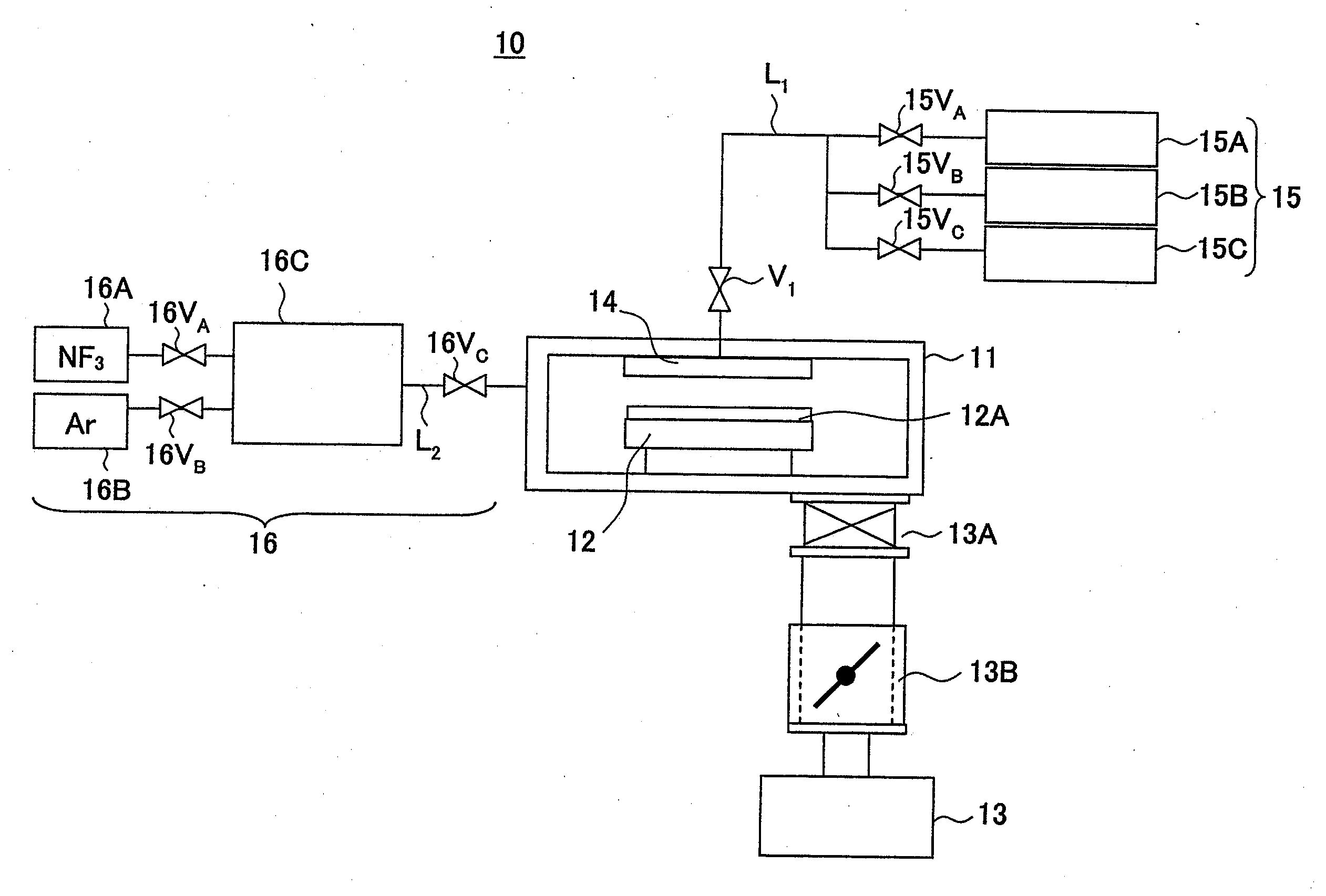
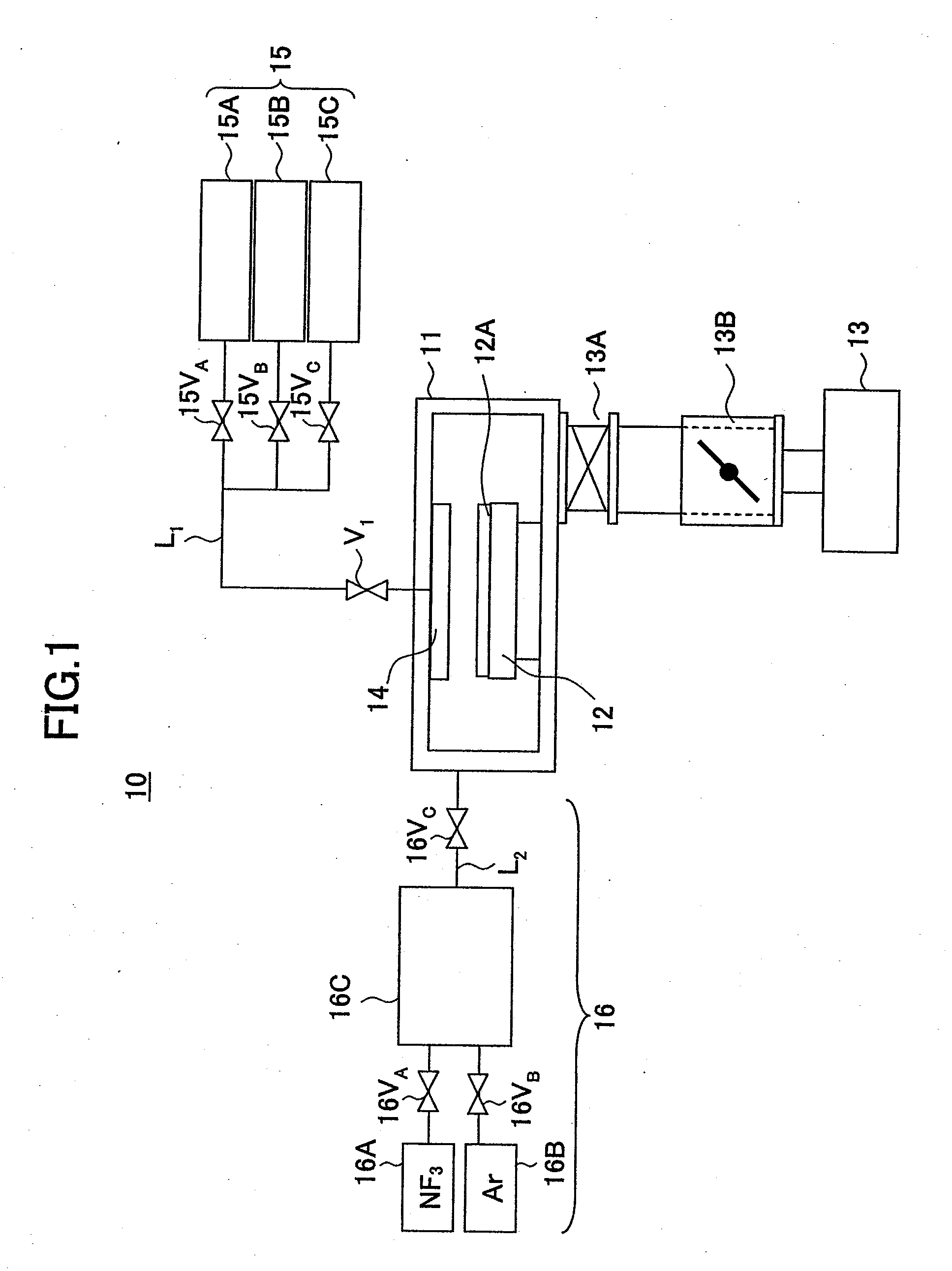
[0165]On the other hand, the pressure or gas flow rate used in actual CVD apparatuses such as the CVD apparatus 10 of FIG. 1 for the cleaning process or etching process is much larger than the ignition point shown in FIG. 9 or 10, and thus, the toroidal plasma generator 60 is required to change the process condition, after the plasma ignition at the ignition point of FIG. 9 or 10, to the process point where the actual process is conducted, without exting...


PUM

PropertyMeasurementUnit
temperatureaaaaaaaaaa
frequencyaaaaaaaaaa

Abstract

A plasma generation method in a toroidal plasma generator that includes a gas passage having a gas entrance and a gas outlet and forming a circuitous path and a coil wound around a part of the gas passage includes the steps of supplying a mixed gas of an Ar gas and an NF3 gas containing at least 5% of NF3 and igniting plasma by driving the coil with a high-frequency power, wherein the plasma ignition step is conducted under a total pressure of 6.65-66.5 Pa.

Description

[0001]This application is a continuation of U.S. application Ser. No. 10 / 562,400 filed on Dec. 27, 2005, which is the U.S. national stage of International Patent Application No. PCT / JP2004 / 009026 filed on Jun. 25, 2004, the entire contents of which is incorporated by reference herein. Priority is claimed based on Japanese Patent Application No. 2003-185160 filed on Jun. 27, 2003, the entire contents of which is incorporated by reference herein, and Japanese Patent Application No. 2003-185161 filed on Jun. 27, 2003, the entire contents of which is incorporated by reference herein.TECHNICAL FIELD[0002]The present invention generally relates to fabrication of semiconductor devices and more particularly to a cleaning method and substrate processing method that uses plasma. Further, the present invention related to a plasma generator and particularly to a plasma ignition method.[0003]Plasma generator is used extensively in fabrication of semiconductor devices or liquid crystal display de...

Claims


Application Information

Patent Timeline
Patent Type & Authority Applications(United States)
IPC IPC(8): B08B9/027H05H1/00B44C1/22B08B7/00C23G5/00H01J37/32H01L21/3065H01L21/311
CPCB08B7/0035C23G5/00H01L21/31116H01J37/32357H01L21/3065H01J37/321H01L21/304
Inventor KANNAN, HIROSHITAMURA, NOBORUDOBASHI, KAZUYA
Owner TOKYO ELECTRON LTD
Why Eureka
Try Eureka