Method for making a silicon quantum dot fluorescent lamp

a fluorescent lamp and quantum dot technology, applied in the manufacture of electric discharge tubes/lamps, cold cathode manufacturing, electromechanical systems, etc., can solve the problems of affecting throughput, hazard to the environment of mercury, complex structure, etc., and achieves efficient heat transfer and a lot of electrons.

Inactive Publication Date: 2010-10-07
INST NUCLEAR ENERGY RES ROCAEC
View PDF6 Cites 10 Cited by
  • Summary
  • Abstract
  • Description
  • Claims
  • Application Information

AI Technical Summary

Benefits of technology

[0011]The primary objective of the present invention is to provide a silicon quantum dot fluorescent lamp that transfer heat efficiently and provides a lot of electrons.

Problems solved by technology

The mercury is however hazard to the environment.
Firstly, a red-light LED, a green-light LED and a blue-light LED are used together. The illuminative efficiency is high. However, the structure is complicated for including many electrodes and wires. The process is complicated for involving many steps of wiring. The wiring could cause disconnection of the wires and damages to the crystalline grains, thus affecting the throughput.
Secondly, a blue-light LED and yellow fluorescent powder are used. The size is small, and the cost low. However, the structure is still complicated for including many electrodes and wires. The process is still complicated for involving many steps of wiring. The wiring could cause disconnection of the wires and damages to the crystalline grains, thus affecting the throughput.
Thirdly, an ultra-light LED and white fluorescent powder are used. The process is simple, and the cost low. However, the resultant light includes two separate spectrums. A red object looks orange under the resultant light because of light polarization. The color-rendering index is poor. Furthermore, the decay of the luminosity is serious. The quality of fluorescent material deteriorates in a harsh environment. The lamp therefore suffers a short light and serious light polarization.
There is another serious problem with the LED-based lamps.
If looking directly at an LED-based lamp, a person will feel very uncomfortable in the eyes because of the intensive light emitted from the LED-based lamp.

Method used


Image

  • Method for making a silicon quantum dot fluorescent lamp
  • Method for making a silicon quantum dot fluorescent lamp
  • Method for making a silicon quantum dot fluorescent lamp

Examples


Embodiment Construction

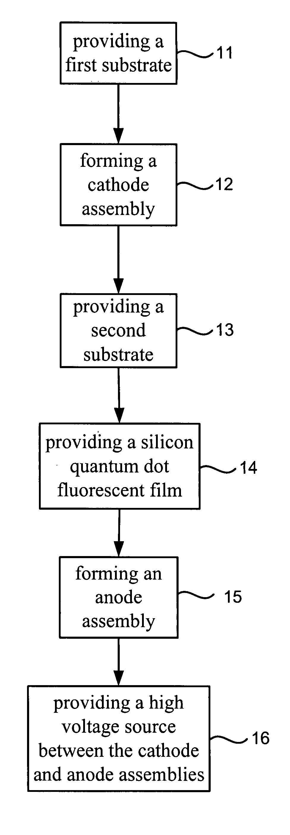
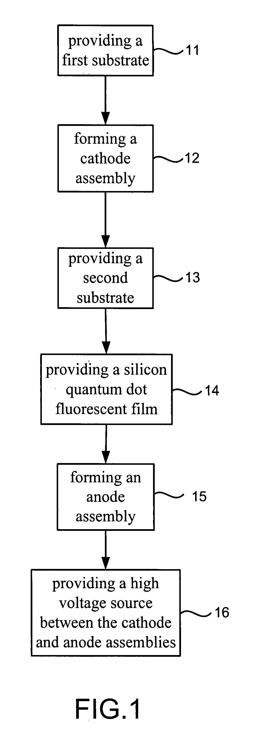
[0030]Referring to FIG. 1, there is shown a method for making a silicon quantum dot fluorescent lamp according to the preferred embodiment of the present invention.

[0031]Referring to FIGS. 1 and 2, at 11, a first substrate 21 is provided. The first substrate 21 may be made of silicon, glass, ceramic or stainless steel.

[0032]Referring to FIGS. 1, 3 and 4, at 12, the first substrate 21 is coated with a buffer layer 22, and the buffer layer 22 is coated with a catalytic layer 23. The coating is done in an e-gun evaporation system or a sputtering system. The buffer layer 22 is made of titanium. The catalytic layer 23 is made of nickel, aluminum or platinum. Referring to FIG. 3, nanometer carbon tubes 24 are provided on the catalytic layer 23 in a chemical vapor deposition (“CVD”) process in which ethane or methane is used as a carbon source. Referring to FIG. 4, instead of the nanometer carbon tubes 24, nanometer silicon wires 25 are provided on the catalystic layer 23 in a CVD process ...


PUM


Abstract

A silicon quantum dot fluorescent lamp is made via providing a high voltage source between a cathode assembly and an anode assembly. The cathode assembly is made by providing a first substrate, coating a buffer layer on the first substrate, coating a catalytic layer on the buffer layer and providing a plurality of nanometer discharging elements on the catalytic layer. The anode assembly is made via providing a second substrate, coating a silicon quantum dot fluorescent film on the second substrate with and coating a metal film on the silicon quantum dot fluorescent film.

Description

BACKGROUND OF INVENTION[0001]1. Field of Invention[0002]The present invention relates to a silicon quantum dot fluorescent lamp and, more particularly, to a method for making a silicon quantum dot fluorescent lamp that efficiently transfers heat and provides a lot of electrons.[0003]2. Related Prior Art[0004]Fluorescent lamps containing mercury are often used. In such a lamp, electricity causes mercury vapor to discharge, thus generating ultraviolet light. The ultraviolet light excites three fluorescent materials to emit red, green and blue light, respectively. The mercury is however hazard to the environment.[0005]In addition to Edison light bulbs and fluorescent lights, light emitting diodes (“LED”) are getting more and more popular. A white-light LED is operated in three patterns as follows:[0006]Firstly, a red-light LED, a green-light LED and a blue-light LED are used together. The illuminative efficiency is high. However, the structure is complicated for including many electrod...

Claims


Application Information

Patent Timeline
Patent Type & Authority Applications(United States)
IPC IPC(8): H01J9/00
CPCH01J63/06H01J63/04
Inventor YANG, TSUN-NENGLAN, SHAN-MINGCHIANG, CHIN-CHENMA, WEI-YANGKU, CHIEN-TE
Owner INST NUCLEAR ENERGY RES ROCAEC
Why Eureka
Try Eureka