Microorganism testing apparatus

a microorganism and testing apparatus technology, applied in the field of microorganism testing apparatus, can solve the problems of increasing background light, increasing cost per measurement, and reducing measurement sensitivity, so as to improve light collection efficiency, increase fluorescence detection intensity, and increase background light emitted

Inactive Publication Date: 2010-10-28
HIATACHI POWER SOLUTIONS CO LTD
View PDF4 Cites 29 Cited by
  • Summary
  • Abstract
  • Description
  • Claims
  • Application Information

AI Technical Summary

Benefits of technology

[0019]The intensity of fluorescence detected from the microorganism detection unit (flow cell) depends on the intensity of fluorescence emitted from each point in space and on the light collection efficiency of an optical system for light emitted from each point in space. Accordingly, the higher the intensity of fluorescence emitted from points in space for which light collection efficiency is higher, the higher the intensity of fluorescence detected by a detection device. Further, a member constituting the microorganism detection unit (flow cell) has a higher fluorescence quantum yield than air, and light collection efficiency is higher for light spots closer to the focal point of the optical system. Accordingly, the intensity of fluorescence detected by the detector is maximum when the microorganism detection unit (flow cell) is positioned near the focal point of the excitation light.
[0020]For the above-described reasons, the intensity of fluorescence detected from the microorganism detection unit (flow cell) can be related to the position of the microorganism detection unit (flow cell) with respect to the excitation light, and the position of the microorganism detection unit (flow cell) can be adjusted. At this time, fluorescence from the microorganism detection unit (flow cell) can be detected by an optical system for detecting microorganisms. This eliminates the necessity of an optical system dedicated for alignment, and prevents the complication of a device and an increase in device cost. Moreover, since fluorescent microparticles are not used in alignment, it is possible to prevent a decrease in measurement sensitivity due to the adhesion of fluorescent microparticles to the wall of the flow path, and also prevent an increase in measurement cost due to the use of fluorescent microparticles.
[0021]These effects are similarly obtained in the case where a mark is provided at a predetermined position in the microorganism testing chip, and where alignment is performed based on the intensity of fluorescence detected by irradiating this mark with the excitation light. In this case, it is necessary to provide the mark of the microorganism testing chip. However, a structure can be employed which increases the intensity of fluorescence without adversely affecting microorganism testing, and a change in fluorescence at the time of alignment can be reliably detected.

Problems solved by technology

However, fluorescent microparticles may adhere to the wall of the detection flow path, and thereby increase background light.
In such a case, since weak fluorescence emitted by fine particles to be measured cannot be detected, measurement sensitivity is expected to decrease.
Moreover, since fluorescent microparticles for alignment are consumed for each measurement, cost per measurement also increases.

Method used


Image

  • Microorganism testing apparatus
  • Microorganism testing apparatus
  • Microorganism testing apparatus

Examples


Embodiment Construction

[0034]Hereinafter, an embodiment of the present invention will be described with reference to the drawings. It should be noted that the undermentioned embodiment of the present invention is one example, and other embodiments can be achieved by combination or replacement with publicly- or well-known techniques.

(A) Example of Overall Configuration of Device

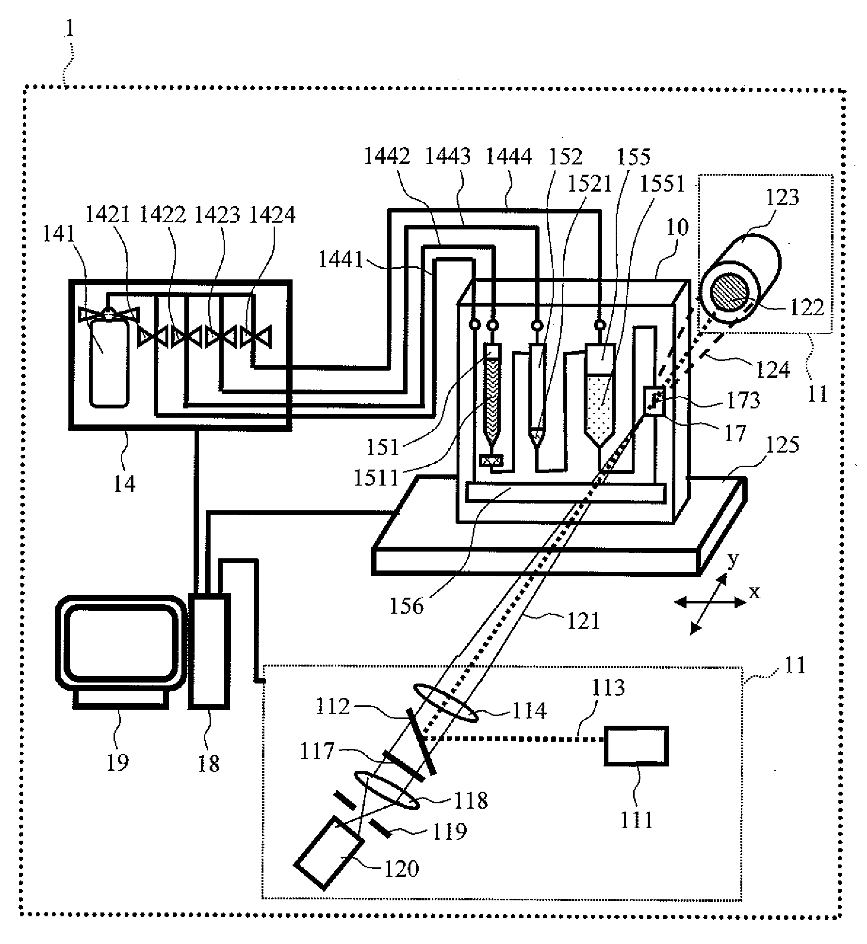
[0035]FIG. 1 shows a configuration diagram of a microorganism testing apparatus 1 according to the embodiment of the present invention. The microorganism testing apparatus 1 includes a microorganism testing chip 10, a pressure supply device 14, an X-Y movable stage 125, and a detection device 11. The microorganism testing chip 10 holds a specimen and a reagent therein, and internally includes a mechanism for performing processes necessary for measuring microorganisms. The pressure supply device 14 controls the transportation of a specimen and a reagent in the microorganism testing chip 10 through chip connection pipes 1441-1444 conn...


PUM

PropertyMeasurementUnit
widthaaaaaaaaaa
thicknessaaaaaaaaaa
lengthaaaaaaaaaa

Abstract

To eliminate the necessity of a dedicated optical system and the flowing of fluorescent microparticles for aligning excitation light with a flat plate-shaped flow cell which internally includes a flow path, a microorganism testing apparatus includes: a first detector that detects fluorescence emitted from microorganisms flowing through a detection flow path when a microorganism detection unit included in a microorganism testing chip is irradiated with excitation light, and converts the fluorescence to an electrical signal; and a second detector that detects scattered light similarly emitted from the microorganisms flowing through the detection flow path, and converts the scattered light to an electrical signal. The alignment of the detection flow path is performed in the direction of the optical axis of the excitation light by controlling and moving a stage having the microorganism testing chip mounted thereon based on the intensity of fluorescence detected by the first detector.

Description

BACKGROUND OF THE INVENTION[0001]1. Field of the Invention[0002]The present invention relates to a microorganism testing apparatus.[0003]2. Related Art[0004]Conventionally, there have been known measuring apparatuses that execute various kinds of methods for quick and simple measurement of the number of viable bacteria. In particular, microorganism measuring apparatuses using a fluorescence flow cytometry method have been known as an approach for quick and direct measurement of the number of viable bacteria.[0005]In the fluorescence flow cytometry method, the flow diameter of a fluid specimen containing microorganisms such as bacteria or plankton dyed with fluorochrome is set small, and microorganisms flowing through a flow path are measured one by one. Some of microorganism measuring apparatuses using this method can measure ten thousand or more microorganisms per minute one by one. Further, microorganism measuring apparatuses using this method employ a technique in which a fluid s...

Claims


Application Information

Patent Timeline
Patent Type & Authority Applications(United States)
IPC IPC(8): C12Q1/04C12M1/34
CPCC12M41/36G01N2015/1477G01N21/6428G01N15/1484
Inventor TAKENAKA, KEINAKAMOTO, HIDEKITAKEI, KAZUOKURIHARA, MASAHIROWATANABE, YUUSUKESAITO, HISAO
Owner HIATACHI POWER SOLUTIONS CO LTD
Why Eureka
Try Eureka