Formation of metal-containing nano-particles for use as catalysts for carbon nanotube synthesis

a carbon nanotube and nanoparticle technology, applied in the field of carbon nanotube synthesis, can solve the problems of significant challenge to the realization of such applications, lack of understanding of cnt growth mechanisms, and the speed of cnt growth using iron silicide particles as catalysts, and achieve the effect of mass cnt growth

Inactive Publication Date: 2010-11-11
KATHOLIEKE UNIV LEUVEN
View PDF1 Cites 26 Cited by
  • Summary
  • Abstract
  • Description
  • Claims
  • Application Information

AI Technical Summary

Benefits of technology

[0009]An advantage of the present invention is to provide a method for the growth of CNT using the method for forming metal-containing particles, e.g. metal-silicide particles or pure metal particles, according to the present invention in which the diameter size of catalyst nanoparticles can be controlled such that growth of CNTs with controllable diameter is obtained.
[0010]It is a further advantage of the present invention that massive growth of CNT using metal-silicide nanoparticles as catalyst can be obtained.
[0011]It is a further advantage of the present invention that (under certain pretreatment and growth conditions) metal-silicide nanoparticles can be obtained which are as catalytically active as pure metal nanoparticles.
[0012]The present invention relates to a method for forming metal-containing catalyst nanoparticles, e.g. metal-silicide nanoparticles or pure metal nanoparticles, with controllable diameter and which form active catalyst nanoparticles, with active catalyst nanoparticles being meant that the formed nanoparticles are suitable to be used as a catalyst for carbon nanotube growth. In other words, “active” is to be understood as being capable of growing / synthesizing a carbon nanotube (no fiber!) onto the formed metal-containing nanoparticles. The growth / creation of a carbon nanotube is a multi-step process of first receiving a carbon source, followed by cracking the C and subsequently growing the carbon nanotube. The initial formation of said metal-containing nanoparticles, e.g. metal-silicide nanoparticles or pure metal nanoparticles, is found to be a key factor in CNT nucleation and subsequent massive growth of the CNT. The metal-containing nanoparticles may be pure metal nanoparticles such as e.g. made of or comprising Ni, Fe or Co or may be metal-silicide nanoparticles such as e.g. made of or comprising Ni-silicide, Fe-silicide or Co-silicide. Most preferred, the metal-containing nanoparticles may be metal-silicide nanoparticles.
[0013]In a first aspect of the invention, a method is provided to form metal-silicide nanoparticles having a diameter smaller than 10 nm on a substrate for use as catalyst in carbon nanotube growth. The formed metal-silicide nanoparticles form active catalyst nanoparticles. With active catalyst nanoparticles is meant that the formed nanoparticles are suitable to be used as a catalyst for carbon nanotube growth.
[0018]Annealing the substrate to form metal-silicide nanoparticles, the barrier layer preventing diffusion of the metal-silicide nanoparticles into the substrate.

Problems solved by technology
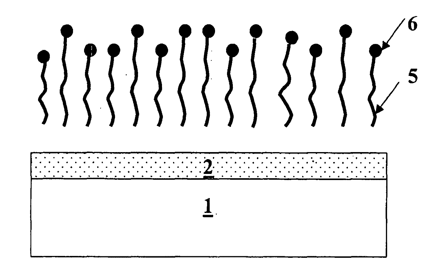
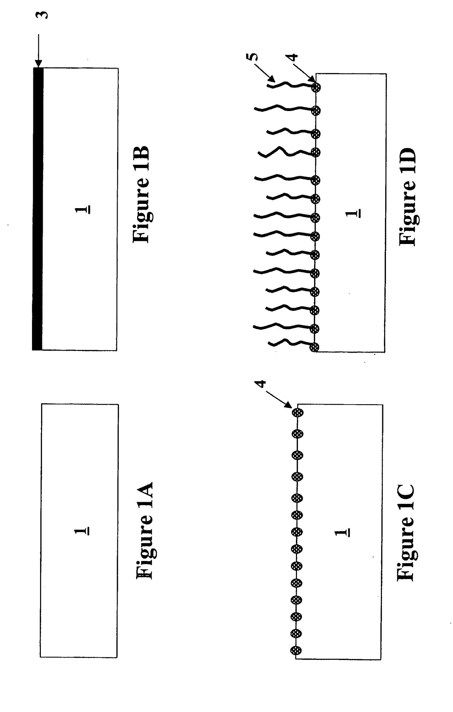
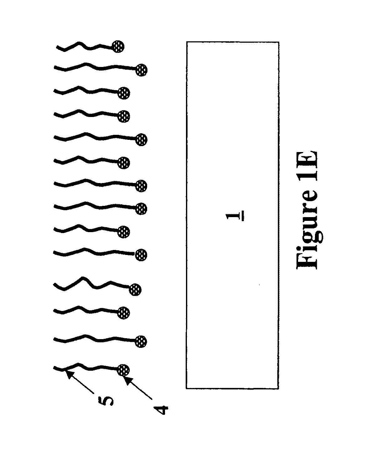
A lack of understanding of CNT growth mechanisms, however, presents a significant challenge to the realization of such applications.
One of the key issues in these growth mechanisms is the formation of catalyst particles (also referred to in this application as nanoparticles) with uniform and controllable diameter to be used in e.g. catalyst mediated chemical vapor deposition processes for CNT growth.
Furthermore, CNT growth using the iron silicide particles as a catalyst was much slower than when the iron particles formed on the barrier layer were used as a catalyst.
Therefore, it was concluded that formation of silicides at the metal / silicon substrate interface should be avoided in order not to decrease the catalyst activity of the formed catalyst particles and thus that metal-silicide particles are not suitable as a catalyst in CNT growth.

Method used


Image

  • Formation of metal-containing nano-particles for use as catalysts for carbon nanotube synthesis
  • Formation of metal-containing nano-particles for use as catalysts for carbon nanotube synthesis
  • Formation of metal-containing nano-particles for use as catalysts for carbon nanotube synthesis

Examples


example 1

Formation of Metal Nanoparticles Versus Formation of Metal-Silicide Nanoparticles on a Silicon Substrate

[0083]Two different substrates were evaluated. The first substrate is a pure Si (100) wafer, the second substrate is a Si (100) wafer with a 50 nm thermal oxide grown on it (in this disclosure referred to as SiO2 surface). Co. Ni or Fe metal films were deposited on said substrates (sputter process) to obtain a 1 nm and 5 nm thin metal film. These substrates comprising the metal films were then annealed in different gas ambients (N2, H2 or 50% N2 / 50% H2) at 600° C. After annealing (as described by the method of this invention) the continuous metal film is transformed into nanoparticles. The temperature of the annealing process to obtain metal-silicide particles turned out to be very important. FIG. 7 illustrates the optimal annealing temperatures for achieving metal-silicide nanoparticles on a Si-substrate for a 1 nm deposited Ni film, a 5 nm deposited Ni film, a 1 nm deposited Co ...

example 2

Comparison of Growth of CNT on Metal Nanoparticles Versus CNT Growth on Metal-Silicide Nanoparticles

[0088]Substrates as described in example 1, comprising metal nanoparticles or metal-silicide nanoparticles were exposed to CNT synthesis conditions comprising C2H4 as carbon source, N2 and H2 as assistant gases. Growth was performed at 600° C. The resulting CNTs were characterized by high-resolution microscopy. The findings of this study reveal that metal films such as Fe, Co and Ni films form nanoparticles that are catalytically active for CNT synthesis on both Si and SiO2 surfaces depending on the pretreatment and synthesis conditions. This implies that metal-silicide formation does not inhibit CNT growth as mentioned in prior art references but instead results in comparable CNT yield when the method for forming metal-silicide nanoparticles of the current invention is used. Overall, these results indicate that the considerable expertise already existing in metal silicides can be app...

example 3

Catalytic Activity of Metal-Silicide Nanoparticles Using a Diffusion Barrier Layer to Avoid Migration of Silicides into the Substrate

[0091]Metal-silicides formed on a silicon substrate can only be used as catalyst for CNT growth in a narrow process window since the temperature has to be limited to avoid growth inhibition. The decomposition temperature of the selected carbon source has to be lower that the growth temperature, otherwise the metal-silicide nanoparticles agglomerate or become embedded in the substrate before CNT growth occurs. It would mean that if Si is replaced by another substrate where agglomeration / diffusion of metal silicide nanoparticles is avoided, these compounds should be in principle active at higher temperatures.

[0092]To prove this assumption, a sample was prepared comprising metal-silicide nanoparticles which were formed on a barrier layer (SiO2). To achieve this, 5 nm of poly-Si, followed by 5 nm Ni were deposited onto 100 nm of thermal oxide (SiO2). The s...


PUM

PropertyMeasurementUnit
diameteraaaaaaaaaa
thicknessaaaaaaaaaa
thicknessaaaaaaaaaa

Abstract

The present invention relates to a method for forming metal-silicide catalyst nanoparticles with controllable diameter. The method according to embodiments of the invention leads to the formation of ‘active’ metal-suicide catalyst nanoparticles, with which is meant that they are suitable to be used as a catalyst in carbon nanotube growth. The nano-particles are formed on the surface of a substrate or in case the substrate is a porous substrate within the surface of the inner pores of a substrate. The metal-silicide nanoparticles can be Co-silicide, Ni-silicide or Fe-silicide particles. The present invention relates also to a method to form carbon nanotubes (CNT) on metal-silicide nanoparticles, the metal-silicide containing particles hereby acting as catalyst during the growth process, e.g. during the chemical vapour deposition (CVD) process. Starting from very defined metal-containing nanoparticles as catalysts, the diameter of grown CNT can be well controlled and a homogeneous set of CNT will be obtained.

Description

FIELD OF INVENTION[0001]The present invention is related to the field of carbon nanotube synthesis. More specifically the invention is related to the formation of metal-containing nanoparticles suitable for being used as a catalyst in carbon nanotube growth.BACKGROUND[0002]Carbon nanotubes (CNT) in general exhibit exceptional electronic and mechanical properties. Therefore, carbon nanotubes are expected to find a big diversity of industrial applications. One of these applications could be the use as both passive and active components in nano-electronics. A lack of understanding of CNT growth mechanisms, however, presents a significant challenge to the realization of such applications. One of the key issues in these growth mechanisms is the formation of catalyst particles (also referred to in this application as nanoparticles) with uniform and controllable diameter to be used in e.g. catalyst mediated chemical vapor deposition processes for CNT growth. Control of the diameter size an...

Claims


Application Information

Patent Timeline
Patent Type & Authority Applications(United States)
IPC IPC(8): H01L21/20B05D3/10B01J21/06B01J23/745B01J23/755B01J23/75B01J27/24B01J37/34
CPCB01J23/74H01L2221/1094B01J23/75B01J23/755B01J35/0013B01J35/006B01J37/0217B01J37/0238B01J37/0244B01J37/08B01J37/347B82Y10/00B82Y30/00B82Y40/00C01B31/0233C01B33/06H01J9/025H01J2201/30469H01L21/28518H01L21/76876H01L21/76879H01L51/0048B01J23/745C01B32/162H10K85/221
Inventor ESCONJAUREGUI, SANTIAGO CRUZWHELAN, CAROLINEMAEX, KAREN
Owner KATHOLIEKE UNIV LEUVEN
Why Eureka
Try Eureka