
Fiber sorbents

a fiber sorbent and sorbent technology, applied in the field of fiber sorbents, can solve the problems of ineffective and commercially attractive methods of removing sulfur compounds, inability to efficiently and effectively remove and inability to achieve hydrogen distribution. effect, the effect of removing low-level contaminants from gas streams both effectively and efficiently

Inactive Publication Date: 2010-12-16
GEORGIA TECH RES CORP
View PDF13 Cites 53 Cited by
  • Summary
  • Abstract
  • Description
  • Claims
  • Application Information

AI Technical Summary

Benefits of technology

[0008]Thus, there is still a need for a material and process which is capable of removing low level contaminants from a gas stream both effectively and efficiently. It would further be beneficial if the material could be made in an efficient manner that does not require complex post-treatment steps.
[0009]Advantageously, the instant invention pertains to a material and process which is capable of removing low level contaminants from a gas stream both effectively and efficiently. Fortunately, the material may be made in a manner that does not require the intricacies of forming an interior barrier layer lining a lumen and its associated problems of potential blockages and capping requirements. And the material may be made efficiently and effectively in a multi-layer spinning process.
[0011]In another embodiment, the invention pertains to a composition suitable for making a sheath on a fiber in an improved multi-layer spinning process. That is, in a multi-layer spinning process for making a sheath on a fiber comprising spinning a sheath dope with a core dope to form a fiber comprising a porous core and a sheath surrounding said porous core the improvement comprises employing a sheath dope composition which comprises a polyvinylidene chloride and a solvent comprising a dipolar aprotic solvent wherein the polyvinylidene chloride comprises at least about 15 weight percent based on the total weight of the composition. This facilitates a solution of the problem in the prior art wherein dilute post-treatment solutions had to be employed to avoid clumping of fibers.

Problems solved by technology

Unfortunately, however, hydrogen distribution is currently lacking since transfer of hydrogen through pipelines in heavily populated areas may prove dangerous.
However, a potential problem with unprocessed pipeline natural gas is that it often may have up to 4-5% hydrogen sulfide (H2S) along with other sulfur compounds.
And unfortunately, common noble metal catalysts for e.g. Nickel, Platinum, and Palladium which are commonly used for reforming may be poisoned by these sulfur compounds when the concentration levels exceed even 1 ppm.
When the concentration of sulfur compounds is on the order of unprocessed pipeline natural gas described above and the scale of operation is relatively small such as in fuel cells, energy intensive processes like amine absorption are not commercially attractive means of removing sulfur compounds.
Other methods such as packed bed sorption using, for example, activated carbon is unattractive since activated carbon becomes pyrophoric when exposed to natural gas while using various metal oxides in packed bed sorption processes may require a high temperature.
The flow of gas on the sheath side and a regenerating media through the bore may result in a pressure drop and / or cause bypass or channeling rendering the fibers useless.
In addition, the complex post-treatment step can result in potential blockages at higher concentrations which may limit the barrier layer.
The method may be useful in reducing the concentrations of CO2 from a high level of around 20% to about 1%, but it is not particularly useful for reducing the concentration to a very low level.
The barrier layer may comprise “polyvinylidene chloride (PVDC), polyacrylonitrile, epichlorohydrin (Hydrin), polyether amide block co-polymer, glass, silica, alumina, metal, metal oxides, latex, other high barrier polymers, co-polymers thereof, or combinations thereof.” Unfortunately, some of these materials may prove difficult to employ and / or may be ineffective or inefficient in certain processes, for example, removing low level contaminants from a gas stream.
They also may prove difficult to use for a suitable exterior barrier layer in some applications due to, for example, poor structural integrity as in the case of glass.

Method used


Image

  • Fiber sorbents
  • Fiber sorbents
  • Fiber sorbents

Examples


examples

Fiber Sorbent Core Dope Preparation in General

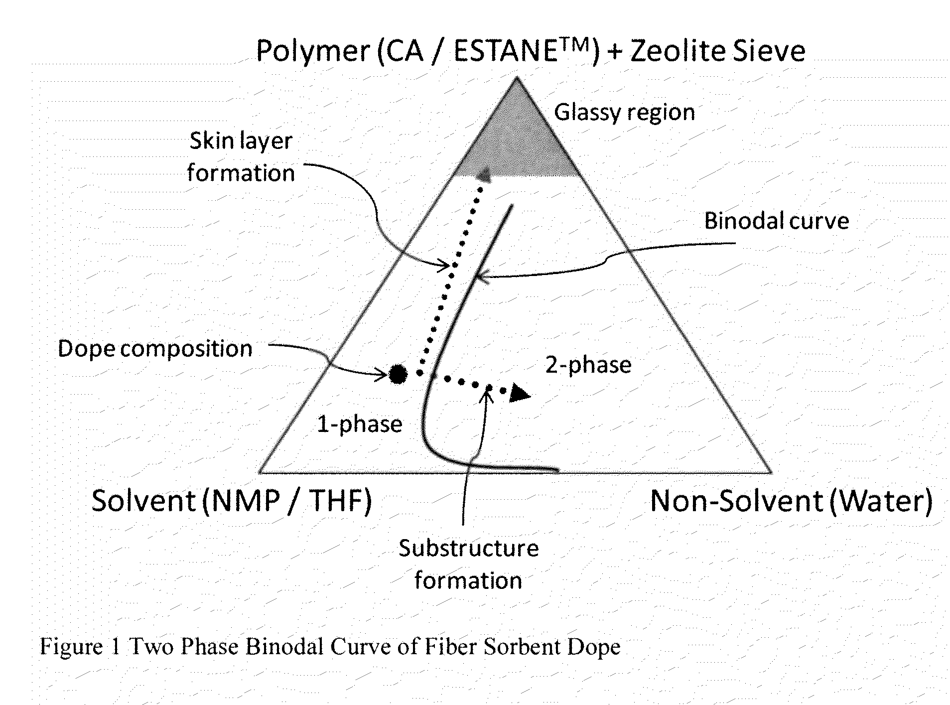
[0065]Fiber sorbent dopes are usually made close to a two phase binodal curve as shown in FIG. 1 to facilitate faster phase separation and higher porosity. Dopes in smaller quantities, e.g., 15 ml, may be made by varying solvent, non-solvent and zeolite composition to determine one and two phase regions using the cloud point technique described in, for example, Kosuri, M. R. and W. J. Koros, Defect free asymmetric hollow fiber membranes from Torlon®, polyamide-imide polymer, for high-pressure CO2 separations. Journal of Membrane Science, 2008. 320(1-2): p. 65-72.

[0066]A dried pore former such as Polyvinyl Pyrrolidone (PVP) is dissolved in a solvent such as N-Methyl-2-Pyrrolidone (NMP) in a 1000 ml glass container using a sonication bath (Model 1510R-MTH, Branson Ultrasonics, Danbury, Conn.). After PVP is completely dissolved, a sorbent, e.g., zeolite NaY (Zeolyst CBV-100, Valley Forge, Pa. with average particle size of about 500 nm and S...


PUM

PropertyMeasurementUnit
Temperatureaaaaaaaaaa

Abstract

The present invention relates to new fibers, new processes of using said fibers, and new sheath dope compositions for multi-layer spinning processes. The fibers comprise a porous core and a sheath surrounding said porous core. The fibers may be useful in, for example, processes for removing low level contaminants like sulfur compounds from a gas stream like natural gas.

Description

RELATED APPLICATIONS[0001]This application claims priority to U.S. provisional application 61 / 186,074 filed Jun. 11, 2009 and U.S. provisional application 61 / 224,009 filed Jul. 8, 2009 which for purposes of U.S. patent practice are each fully incorporated herein by reference to the extent not inconsistent with this application.FIELD OF THE INVENTION[0002]Provided herein are new fibers and processes of using said fibers for removing low level contaminants like sulfur compounds from a gas stream like natural gas. Also, provided are compositions suitable for making a sheath on a fiber made in, for example, a multi-layer spinning process.BACKGROUND AND SUMMARY OF THE INVENTION[0003]High global demand, national security and climate change issues related to conventional fossil fuels have contributed to a need for more environmentally benign fuels. As such fuel-cells such as proton exchange membrane fuel cell (PEMFC) and solid oxide fuel cell (SOFC) have, been explored. However, while both...

Claims


Application Information

Patent Timeline
IPC IPC(8): B01D53/02D01F8/04B01J20/26B01J29/04
CPCB01D53/02B01D53/04B01D2253/102B01D2253/104B01D2253/106B01D2253/108B01D2253/112B01D2253/202B01D2253/304B01D2257/30B01D2257/708B01D2258/06B01J20/08B01J20/10B01J20/18B01J20/20B01J20/28011B01J20/28023B01J20/28061B01J20/3268B01J20/327B01J20/3272B01J20/3293B01J2220/46B29K2027/08C10G25/003D01D5/247D01F8/10B01J20/3458B01J20/3475B01J20/3408B01J20/3416B01J20/3433B01J20/3425B01J20/261B01J20/262
Inventor KOROS, WILLIAM JOHNBHANDARI, DHAVAL A.
Owner GEORGIA TECH RES CORP
Learn More